•
68-Pin Connector (2)-Supports up to 8 RS-232 interfaces in full or half duplex mode using 4 RS-232
connectors (DB-25, DB-9, or RJ-45)
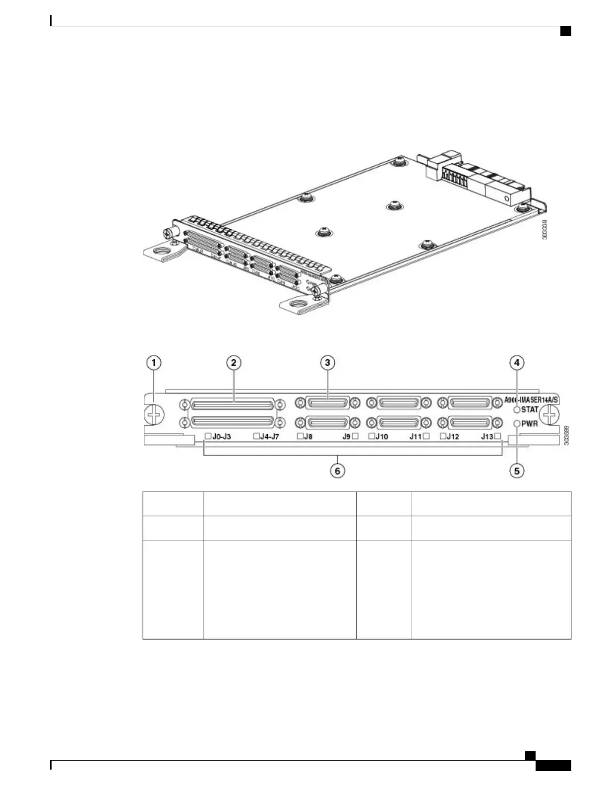
Figure 32: Serial Interface Module
Figure 33: 14-port Serial Interfacce Module Front Panel
68-Pin Connector (2)2Captive screws (2)1
Status (STAT) LED412-in-1 Connector (6)3
LEDs-The LEDs are as follows:
•
J0-J3 and J4-J7-Indicate the
function of the 68-pin connectors
• •
J8-J13-Indicate the status of
the 12-in-1 connectors
6Power (PWR) LED5
For more information about using the LEDs to troubleshoot the Cisco ASR 903 Router, see LED Summary
Cisco ASR 903 Aggregation Services Router Hardware Installation Guide
41
Cisco ASR 903 Router Overview
Interface Modules

 Loading...


