This product requires short-circuit (overcurrent) protection, to be provided as part of the building installation.
Install only in accordance with national and local wiring regulations.
Caution
The Cisco ASR 903 Router installation must comply with all the applicable codes and is approved for use
with copper conductors only. The ground bond fastening hardware should be of compatible material and
preclude loosening, deterioration, and electrochemical corrosion of hardware and joined material.
Attachment of the chassis ground to a central office or other interior ground system must be made with a
6 AWG gauge wire, copper ground conductor at a minimum.
Note
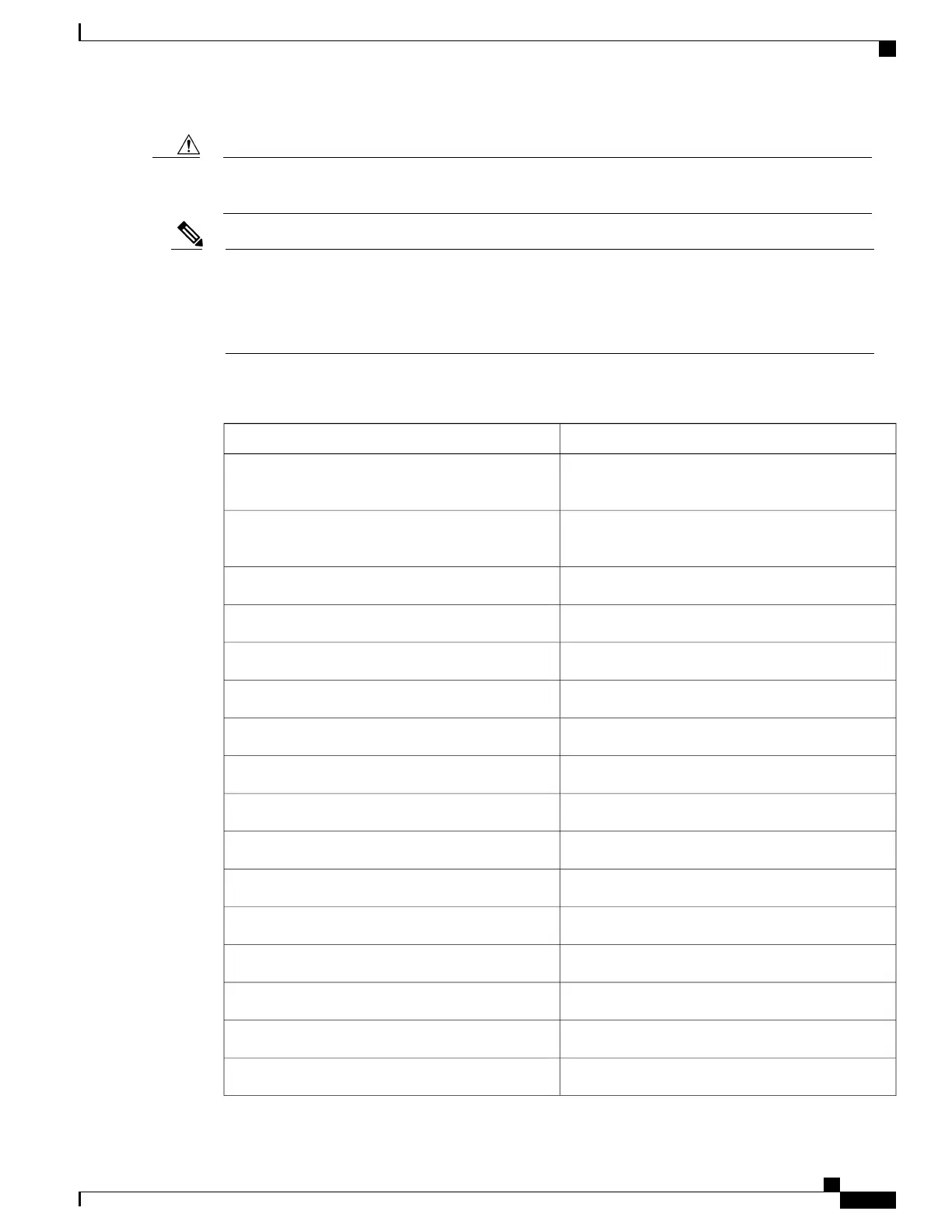
The maximum power draw of the Cisco ASR 903 Router chassis and its configurable hardware components
are listed in the following table. The maximum power draw values are not affected by whether the router
chassis contains 1 or 2 power supplies AC or DC.
Maximum power draw valueHardware component(s)
195 WRouter chassis with 2 power supplies, 1 fan tray, and
1 RSP1A
210 WRouter chassis with 2 power supplies, 1 fan tray, and
1 RSP1B
100 WA900-RSP1A-55 (standby)
100 WA900-RSP1B-55 (standby)
70 WA900-RSP2A-64 (active)
55 WA900-RSP2A-64 (standby)
100 WA900-RSP2A-128 (active)
85 WA900-RSP2A-128 (standby)
230 WA900-RSP3-400-S (active)
230 WA900-RSP3-400-S (standby)
160 WA900-RSP3-200-S (active)
160 WA900-RSP3-200-S (standby)
13.0 WA900-IMA1X (1-port 10 GE XFP interface module)
17.5 WA900-IMA8T (8-port 1 GE RJ45 interface module)
17.5 WA900-IMA8S (8-port 1 GE SFP interface module)
14.5 WA900-IMA8D (8-port T1/E1 interface module)
Cisco ASR 903 Aggregation Services Router Hardware Installation Guide
67
Preparing for Installation
Site Power Guidelines

 Loading...


