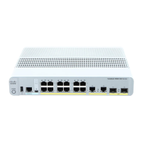
Connecting the Console Port of the Switch
Before You Begin
Before you can configure the switch for basic operations, you need to connect it to a PC that uses a VT-100
terminal emulation program (such as HyperTerminal, ProComm, Minicom, or Tip).
Step 1
Connect one end of a null-modem serial cable to the switch's RJ-45 console port and the other end to your PC's serial
port.
Step 2
Plug the AC power cord into the switch and a grounded 100 to 240 VAC, 50/60-Hz electrical outlet. Turn on the power
supply. The bootup script displays operating system software initialization (code download and power-on self-test
verification) and basic configuration. If the switch passes the power-on self-test, the bootup script runs the configuration
wizard, which prompts you for basic configuration input.
Step 3
Enter yes. Proceed with basic initial setup configuration parameters in the CLI setup wizard. Specify the IP address for
the service port which is the gigabitethernet 0/0 interface.
After entering the configuration parameters in the configuration wizard, you can access the Web GUI. Now, the switch
is configured with the IP address for service port.
Logging On to the Web GUI
Enter the switch IP address in your browser’s address bar. For a secure connection, enter https://ip-address. For a less
secure connection, enter http://ip-address.
Enabling Web and Secure Web Modes
Step 1
Choose Configuration > Switch > Management > Protocol Management > HTTP-HTTPS.
The HTTP-HTTPS Configuration page appears.
Step 2
To enable web mode, which allows users to access the switch GUI using “http://ip-address,” choose Enabled from the
HTTP Access drop-down list. Otherwise, choose Disabled. Web mode (HTTP) is not a secure connection.
WLAN Configuration Guide, Cisco IOS XE Release 3E (Catalyst 3650 Switches)
OL-32353-01 15
Using the Web Graphical User Interface
Connecting the Console Port of the Switch
 Loading...


