Step 1 Connect the two connectors on one end of the cable to the PCIE-A1 and PCIE-A2 connectors on the drive backplane.
Step 2 Route the cables through the chassis cable guides to the rear of the server as shown below.
Step 3 Connect the single connector on the other end of the cable to the PCIE-FRONT connector on PCIe riser 2.
Figure 19: PCIe Cabling to Drive Backplane
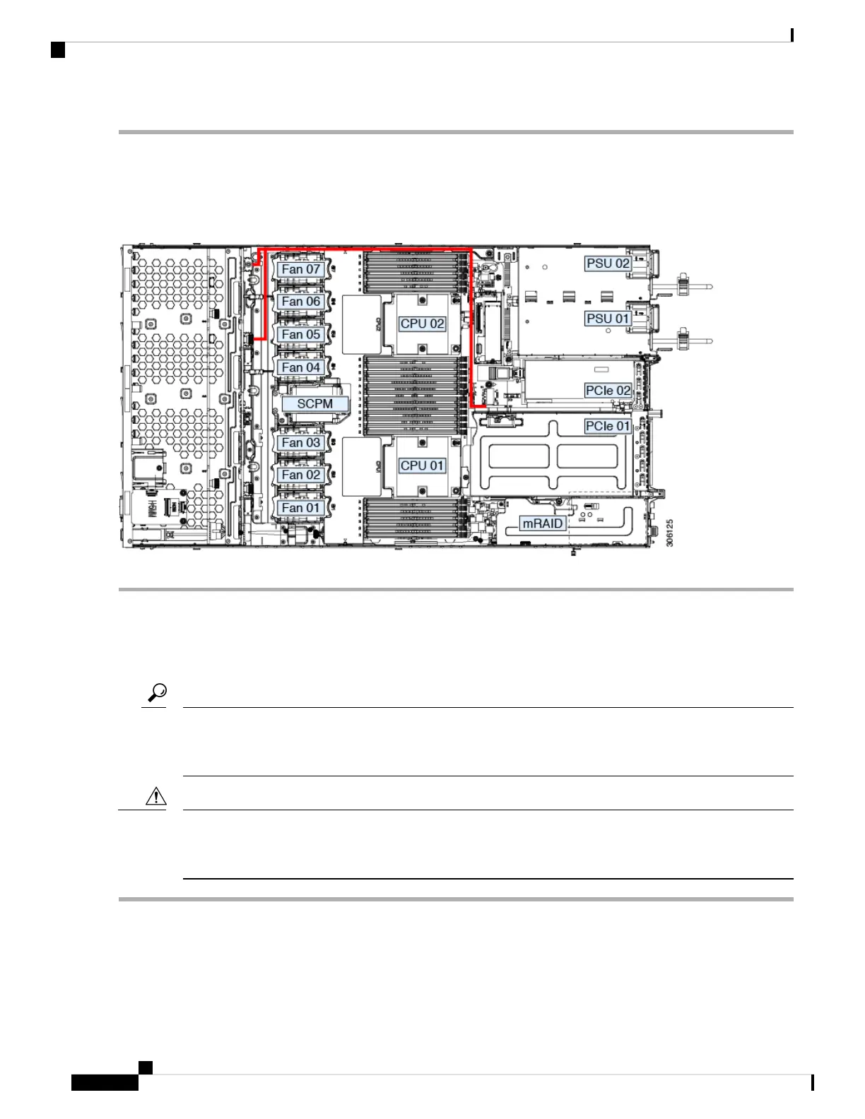
Replacing Fan Modules
The seven fan modules in the server are numbered as shown in the figure 1.
Each fan module has a fault LED next to the fan connector on the motherboard. This LED lights green when
the fan is correctly seated and is operating OK. The LED lights amber when the fan has a fault or is not
correctly seated.
Tip
You do not have to shut down or remove power from the server to replace fan modules because they are hot-
swappable. However, to maintain proper cooling, do not operate the server for more than one minute with
any fan module removed.
Caution
Step 1 Remove an existing fan module:
a) Slide the server out the front of the rack far enough so that you can remove the top cover. You might have to detach
cables from the rear panel to provide clearance.
If you cannot safely view and access the component, remove the server from the rack.
Caution
Cisco Application Services Engine Hardware Installation Guide
38
Maintaining the Server
Replacing Fan Modules
 Loading...