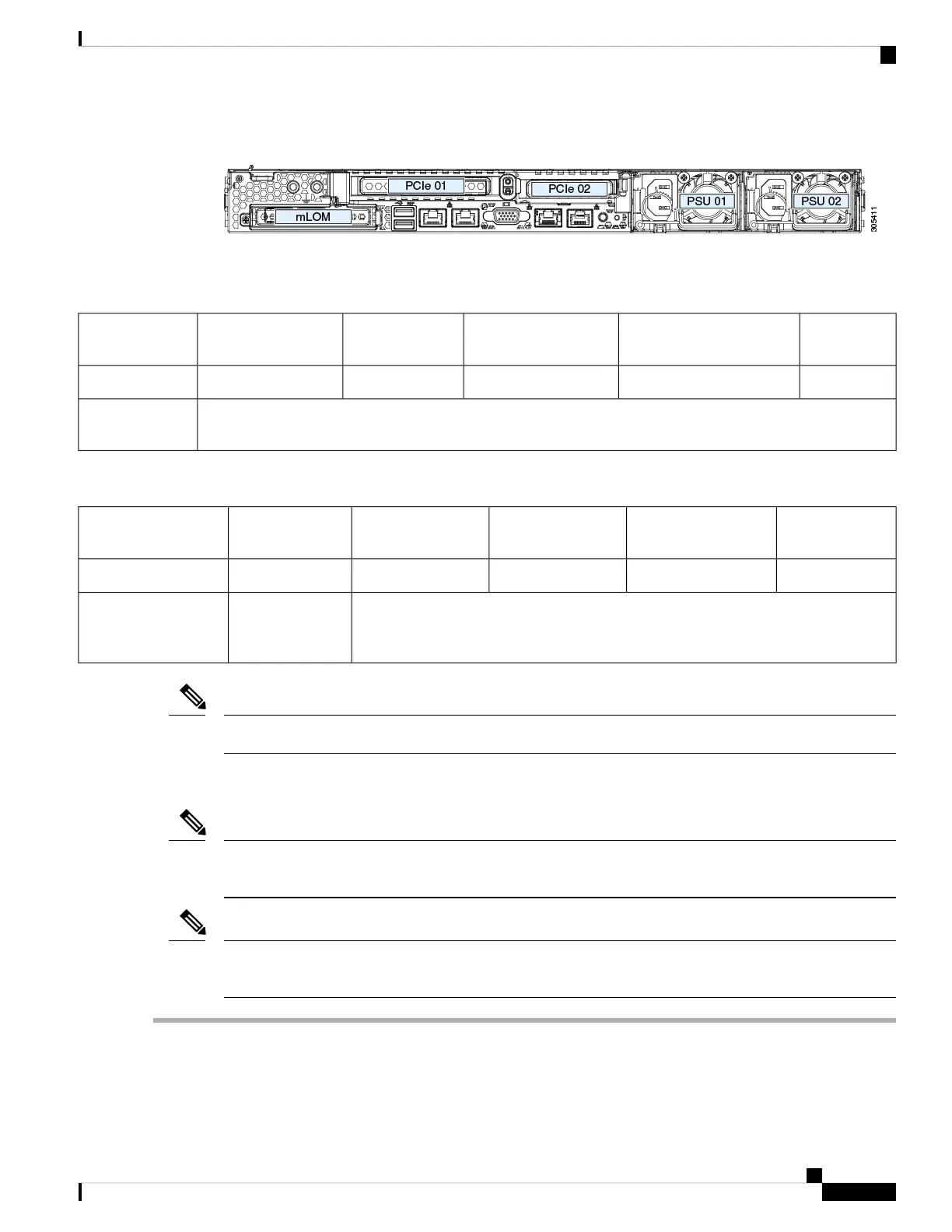
Figure 34: Rear Panel, Showing PCIe Slot Numbering
The following tables describe the specifications for the slots.
Table 5: PCIe Riser 1/Slot 1
NCSI SupportCard Height (Rear Panel
Opening)
Maximum Card LengthConnector LengthElectrical Lane WidthSlot Number
YesFull-height¾ lengthx24 connectorGen-3 x161
One socket for Micro SD cardMicro SD card
slot
Table 6: PCIe Riser 2/Slot 2
NCSI SupportCard Height (Rear
Panel Opening)
Maximum Card
Length
Connector LengthElectrical Lane
Width
Slot Number
Yes½ height½ lengthx24 connectorGen-3 x162
Other end of cable connects to front drive backplane to support front-panel NVMe
SSDs.
Gen-3 x8PCIe cable connector
for front-panel NVMe
SSDs
Riser 2/Slot 2 is not available in single-CPU configurations.
Note
Replacing a PCIe Card
If you are installing a Cisco Virtual Interface Card, there are prerequisite considerations. See Cisco Virtual
Interface Card (VIC) Considerations, on page 64.
Note
RAID controller cards install into a separate mRAID riser. See Replacing a SAS Storage Controller Card
(RAID or HBA), on page 69.
Note
Step 1 Remove an existing PCIe card (or a blank filler panel) from the PCIe riser:
a) Shut down and remove power from the server as described in Shutting Down and Removing Power From the Server,
on page 27.
Cisco Application Services Engine Hardware Installation Guide
61
Maintaining the Server
Replacing a PCIe Card
 Loading...