ENGLISH
GB
65
marked ”OUT” of face C. The power supply cable is for connection to the
power mains.
Face E: the 4 brass threads form the seat for the 4 support feet in the
case of horizontal installation. The 1” cap has the main function of empty-
ing the system. There are also 2 ventilation grids.
Face F: as indicated by the label to be removed, the 1” cap has a dual
function: in the case of horizontal installation, the outlet that is closed by
the cap acts as the system’s loading door (see below “loading opera-
tions”, par. 2.2.3); in the case of vertical installation, the same outlet can
act as the input hydraulic connection (exactly like the one marked “IN” on
face C and as an alternative to it). The user interface panel is composed
of a display and a keyboard and its function is to set the system, query its
status and communicate any alarms.
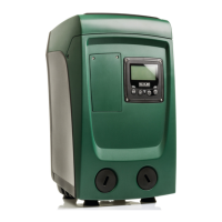
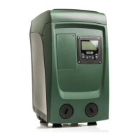
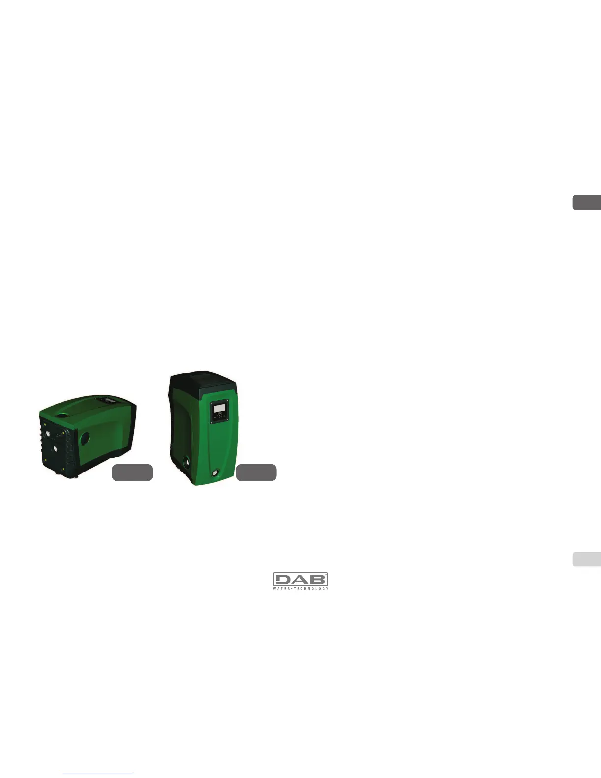
7KHV\VWHPFDQEHLQVWDOOHGLQGLIIHUHQWFRQ¿JXUDWLRQVKRUL]RQWDO
(Fig.4) or vertical (Fig.5).
1.1 Description of the Integrated Inverter
The electronic control integrated in the system is of the type with inverter
DQGLWPDNHVXVHRIÀRZSUHVVXUHDQGWHPSHUDWXUHVHQVRUVDOVRLQWH-
grated in the system.
By means of these sensors the system switches on and off automati-
cally according to the utility’s needs and it is able to detect conditions of
malfunction, to prevent and indicate them.
Figure 4
Figure 5
The Inverter control ensures different functions, the most important of
which, for pumping systems, are the maintaining of a constant pressure
value in delivery and energy saving.
7KHLQYHUWHULVDEOHWRNHHSWKHSUHVVXUHRIDK\GUDXOLFFLUFXLW
constant by varying the rotation speed of the electropump.
In operation without an inverter the electropump is unable to
PRGXODWHDQGZKHQWKHUHLVDQLQFUHDVHRIWKHUHTXHVWIRUÀRZ
the pressure necessarily decreases, or vice versa; this means the
SUHVVXUHVDUHWRRKLJKDWORZÀRZUDWHVRUWRRORZZKHQWKHUHLV
DQLQFUHDVHGUHTXHVWIRUÀRZ
%\YDU\LQJWKHURWDWLRQVSHHGDFFRUGLQJWRWKHLQVWDQWDQHRXV
request of the utility, the inverter limits the power supplied to the
electropump to the minimum necessary to ensure that the re-
TXHVWLVVDWLV¿HG,QVWHDGRSHUDWLRQZLWKRXWDQLQYHUWHUFRQWHP-
plates operation of the electropump always and only at maximum
power.
7KHV\VWHPLVFRQ¿JXUHGE\WKHPDQXIDFWXUHUWRVDWLVI\WKHPDMRULW\RI
installation cases, that is:
Operation at constant pressure;
Set-Point (desired value of constant pressure:SP = 3.0 bar
Reduction of pressure to restart: RP = 0.3 bar
Anti-cycling function: Disabled
However, these parameters and others can be set according to the
system. All the settable values are illustrated in the par. 5-6-7: pressure,
intervention of protections, rotation speed, etc.
There are many other operating modes and accessory functions. Thanks
WRWKHGLIIHUHQWSRVVLEOHVHWWLQJVDQGWKHDYDLODELOLW\RIFRQ¿JXUDEOHLQSXW
and output channels, it is possible to adapt the inverter operation to the
requirements of various systems. See 5-6-7.
1.2 Integrated Expansion Vessel
The system is complete with an integrated expansion vessel with a total
capacity of 2 litres. The main functions of the expansion vessel are:
 Loading...