ENGLISH
GB
69
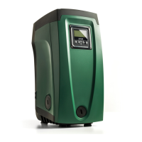
7KHGLVWDQFHRIDWOHDVWPPEHWZHHQ)DFH(RIWKH
system and any wall is obligatory to ensure ventilation
through the grids provided.
7KHGLVWDQFHRIDWOHDVWPPEHWZHHQ)DFH%RIWKHV\VWHP
and an obstruction is recommended so as to be able to carry out
maintenance on the non-return valve without disconnecting the
system.
7KHGLVWDQFHRIDWOHDVWPPEHWZHHQ)DFH$RIWKHV\VWHP
and an obstruction is recommended so as to be able to remove
the door and gain access to the technical compartment.
,IWKHVXUIDFHLVQRWÀDWXQVFUHZWKHIRRWWKDWLVQRWWRXFKLQJDQGDGMXVW
its height until it contacts the surface so as to ensure the stability of the
system. The system must in fact be placed in a safe and stable position,
ensuring that its axis is vertical: it must not be in an inclined position.
2.1.1 Hydraulic connections
Make the connection at input to the system through the mouth on Face
F marked “IN” in Fig.8 (suction connection). Then remove the respective
cap with the aid of the accessory tool or with a screwdriver.
Make the connection at output from the system through the mouth on
7KHYROWDJHDQGIUHTXHQF\RQWKHSXPS¶VWHFKQLFDOGDWD
7KHHOHFWULFDOFRQQHFWLRQLVPDGHLQDGU\SODFHIDUIURP
DQ\SRVVLEOHÀRRGLQJ
The electrical system is provvided with a differential switch
ZLWK,ǻQP$DQGWKDWWKHHDUWKV\VWHPLVHI¿FLHQW
SXPSHGLQVWDOOD¿OWHURQWKHV\VWHPLQWDNHWKDWLVVXLWDEOHIRUFDWFKLQJ
7KHLQVWDOODWLRQRID¿OWHURQLQWDNHFDXVHVDGHFUHDVHRIWKH
FDXVHGE\WKH¿OWHULWVHOIJHQHUDOO\WKHJUHDWHUWKH¿OWHULQJ
&KRRVHWKHW\SHRIFRQ¿JXUDWLRQ\RXLQWHQGWRXVHYHUWLFDORUKRUL]RQWDO
2WKHUW\SHVRILQVWDOODWLRQFRQ¿JXUDWLRQDUHSRVVLEOHXVLQJ'$%DFFHV
9HUWLFDO&RQ¿JXUDWLRQ
w them fully into their brass seats on face C. Put the system in place,
10 mm
200 mm
270 mm
IN
OUT
580 mm
355 mm
265 mm
Figure 8
Face F marked “OUT” in Fig.8 (delivery connection). Then remove the
respective cap with the aid of the accessory tool or with a screwdriver.
All the hydraulic connections of the system to the plant to which it can be
connected are of the threaded female type 1” GAS, made of brass.
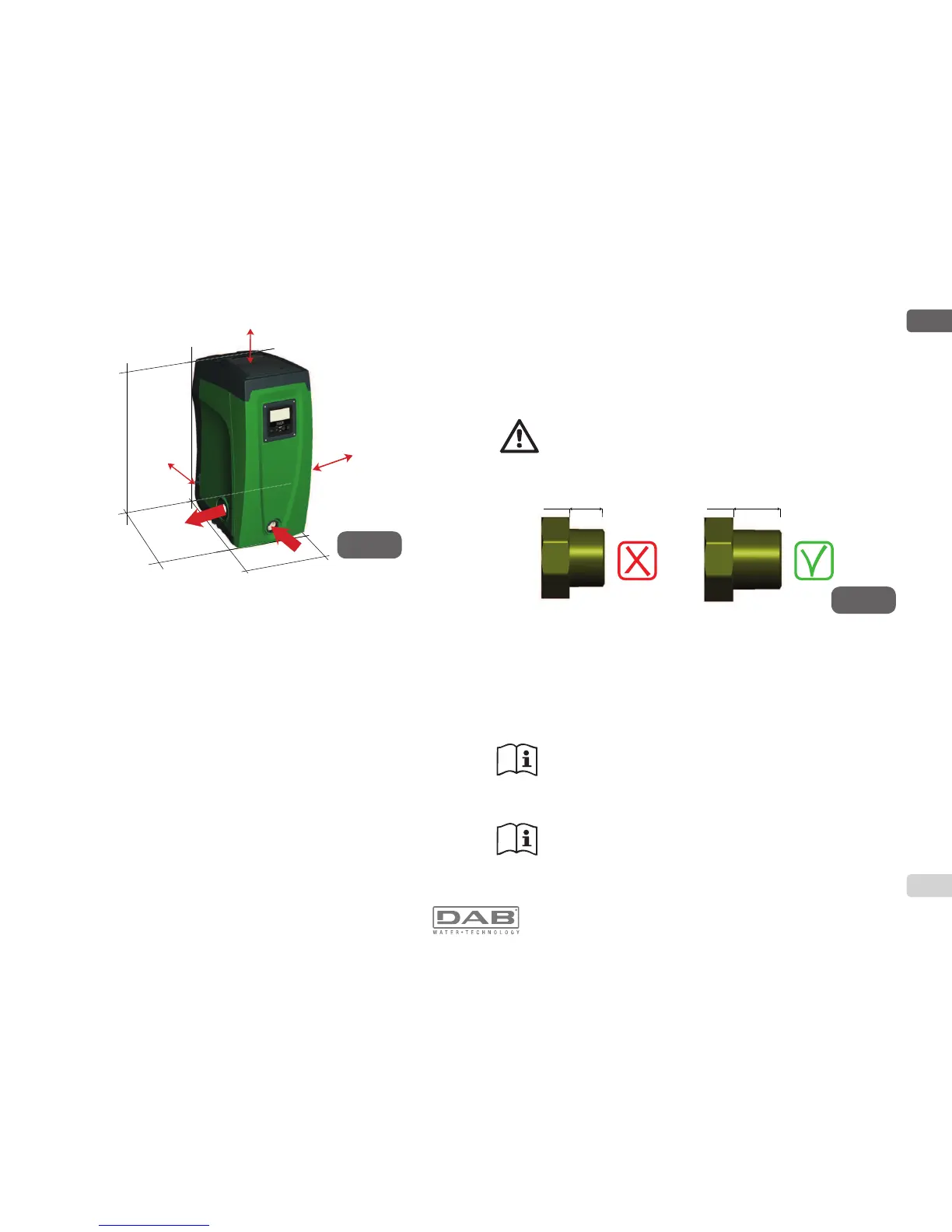
II\RXLQWHQGWRFRQQHFWWKHSURGXFWWRWKHSODQWZLWK¿WWLQJVWKDW
have a diameter larger than the normal 1” pipe (for example the
ULQJQXWLQWKHFDVHRI¿WWLQJVLQSLHFHVPDNHVXUHWKDWWKH´
Gas male thread of the coupling protrudes at least 25mm from
the above diameter (see Fig.9)
With reference to its position with respect to the water to be pumped, the
LQVWDOODWLRQRIWKHV\VWHPPD\EHGH¿QHG³DERYHKHDG´RU³EHORZKHDG´
,QSDUWLFXODUWKHLQVWDOODWLRQLVGH¿QHG³DERYHKHDG´ZKHQWKHSXPSLV
placed at a level higher than the water to be pumped (e.g. pump on the
surface and water in a well); vice versa it is “below head” when the pump
is placed at a level lower than the water to be pumped (e.g. overhead
cistern and pump below).
If the vertical installation of the system is of the “over head”
W\SHLWLVUHFRPPHQGHGWR¿WDQRQUHWXUQYDOYHLQWKHVXFWLRQ
section of the system; this is to allow the operation of loading
the system (par. 2.1.2).
If the installation is of the “over head” type, install the suction
pipe from the water source to the pump in such a way as to
avoid the formation of goosenecks or siphons. Do not place the
suction pipe above the pump level (to avoid the formation of air
bubbles in the suction pipe). The suction pipe must draw at its
< 25 mm > 25 mm
Figure 9
 Loading...