79
79
Input wiring (J5)
Input connected to clean contact
Input connected to
voltage signal
Input
Clean contact
between pins Jumper Signal connection pin
I1 8 - 2 1 – 3 2 - 3
I2 8 - 4 1 – 3 3 - 4
I3 8 - 5 1 – 6 5 - 6
I4 8 - 7 1 – 6 6 - 7
Referring to the example proposed in Figure 2 and using the factory set-
tings for the inputs (I1 = 1; I2 = 3; I3 = 5; I4=10) we obtain:
:KHQWKHVZLWFKFORVHVRQ,WKHSXPSJRHVLQWREORFNVWDWXV
and indicates “F1”
HJ,FRQQHFWHGWRDÀRDWVHHSDU±6HWWLQJH[WHUQDO
ÀRDWIXQFWLRQ
:KHQWKHVZLWFKFORVHVRQ,WKHUHJXODWLQJSUHVVXUHEHFRPHV
“P2”.
(see par. 7.7.8.3 – Setting auxiliary setpoint input function).
:KHQWKHVZLWFKFORVHVRQ,WKHSXPSJRHVLQWREORFNVWDWXV
and indicates “F3”
(see par. 7.7.8.4 – Setting system enabling and fault reset).
:KHQWKHVZLWFKFORVHVRQ,DIWHUWLPH7WKHSXPSJRHVLQWR
block status and indicates “F4”
(see par. 7.7.8.5 – Setting low pressure detenction (KIWA).
The example proposed in Figure 2 refers to the connection with a clean
contact using the internal voltage to control the inputs (of course only the
useful inputs can be used).
Table 6: Input connection
If you have a voltage instead of a contact, it can still be used to control
WKHLQSXWVLWZLOOEHVXI¿FLHQWQRWWRXVHWKH96DQG*1'WHUPLQDOVDQG
to connect the source of voltage, which respects the characteristics de-
scribed in Table 2, to the desired input . If an external voltage is used to
control the inputs, all the circuitry must be protected by double insulation.
ATTENTION: the pairs of inputs I1/I2 and I3/I4 have one pole in
common for each pair.
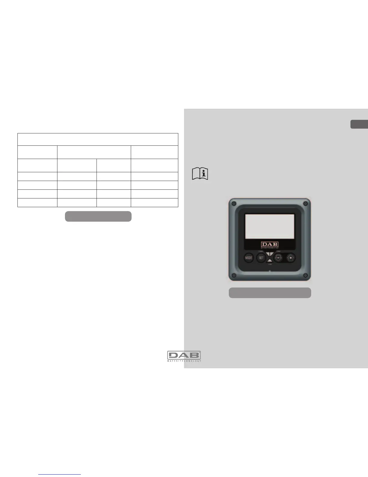
6 - THE KEYPAD AND THE DISPLAY
The user interface is composed of a keypad with 128x240 pixel LCD
display and with POWER, COMM, ALARM warning leds as can be seen
in Figure 3.
The display shows the values and the statuses of the device, with indica-
tions on the functionality of the various parameters.
The functions of the keys are summed up in Table 4.
Figure 15: Aspect of the user interface
ENGLISH
GB

 Loading...