ENGLISH
GB
64
RESPONSIBILITY
The Manufacturer does not vouch for correct operation of
the electropumps or answer for any damage that they may
FDXVHLIWKH\KDYHEHHQWDPSHUHGZLWKPRGL¿HGDQGRUUXQ
outside the recommended work range or in contrast with
other indications given in this manual.
The Manufacturer declines all responsibility for possible
errors in this instructions manual, if due to misprints or
errors in copying. The Manufacturer reserves the right to
PDNHDQ\PRGL¿FDWLRQVWRSURGXFWVWKDWLWPD\FRQVLGHU
necessary or useful, without affecting their essential char-
acteristics.
1- GENERAL
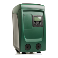
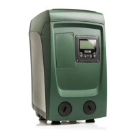
The product is an integrated system composed mainly of a self-priming
multi-stage centrifugal electropump, an electronic control unit that
controls it and an expansion vessel.
Applications
Water systems supply and pressure boosting domestic use or industrial
use.
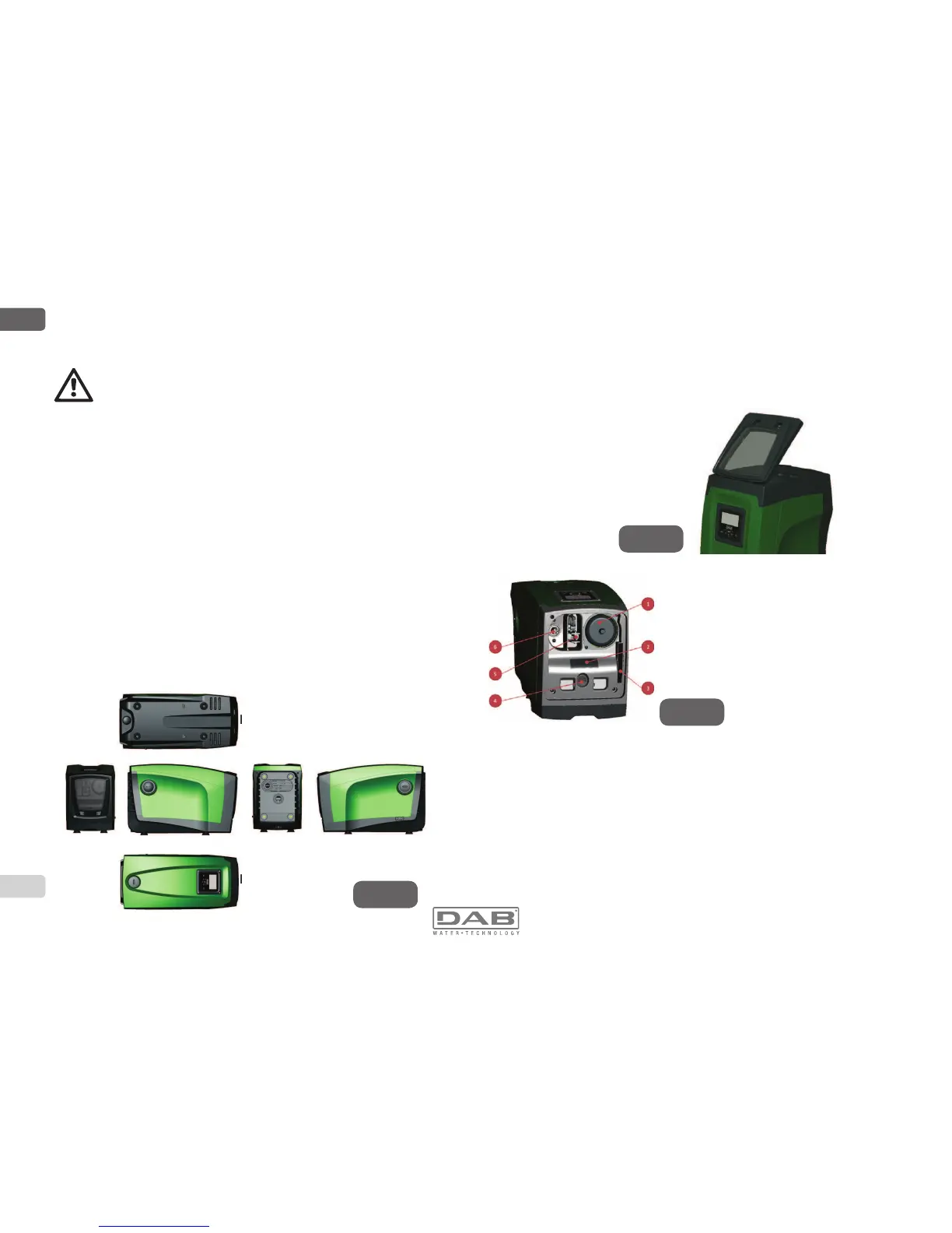
On the outside the product appears as a parallelepiped that presents 6
faces as shown in Fig.1.
A B C D
E
F
Figure 1
Face A: a door allows access to the Technical Compartment. The door
FDQEHUHPRYHGE\LQVHUWLQJ¿QJHUVLQWKHUXEEHUJULSVVTXHH]LQJDQG
rotating the door around the hinges on the side opposite the grips (see
Fig.2). To put the door back in place, insert the hinges in their slots and
close the door until it clicks.
Inside the technical compartment you can access (see Fig.3):
1. Valve of the expansion vessel;
2. Technical data plate;
3. Rapid Guide;
4. Motor shaft;
5. Accessory tool;
6. Filling cap (only for vertical
FRQ¿JXUDWLRQ
Face B: a removable screw cap gives access to the non return valve (see
par. 10.3). Remove it only in the case of maintenance by skilled personnel.
Face C: the 4 brass threads form the seat for the 4 support feet in the
case of vertical installation. The two 1” screw caps can be removed to
make the connections towards the system, depending on the installation
FRQ¿JXUDWLRQ\RXZDQWWRDGRSW,IDSSOLFDEOHFRQQHFWWRWKHFRQQHF-
tion marked “IN” the system from which you want to draw water (well,
cistern,…) and connect the delivery system to the connection marked
“OUT”. There is also a ventilation grid.
Face D: removing the 1” cap allows access to a second delivery con-
nection which can be used at the same time or alternatively to the one
Figure 2
Figure 3
 Loading...