ENGLISH
GB
85
If the case occurs the following may appear:
Fault indications
Warning indications
Indications of the functions associated with the inputs
6SHFL¿FLFRQV
The error or status conditions that can be seen on the main page are
listed in Table 7.
Error or status conditions shown on the main page
Identifying code Description
GO Motor running
SB Motor stopped
BL Blockage due to water lack
PB %ORFNDJHGXHWRVXSSO\YROWDJHRXWVLGHVSHFL¿FDWLRQV
OC Blockage due to overcurrent in the electropump motor
SC Blockage due to short circuit on the output phases
OT Blockage due to overheating of the power stages
BP Blockage due to fault of the pressure sensor
NC Pump not connected
F1 Float function status / alarm
F3 System disable function status / alarm
F4 Low pressure signal function status / alarm
P1 Operating status with auxiliary setpoint 1
P2 Operating status with auxiliary setpoint 2
P3 Operating status with auxiliary setpoint 3
P4 Operating status with auxiliary setpoint 4
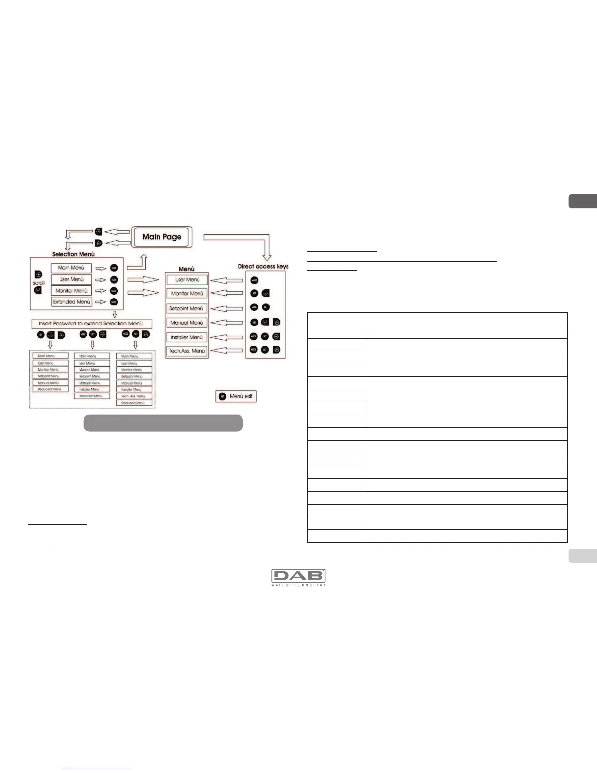
6.3 - Structure of the menu pages
When switched on, some presentation pages are displayed showing the
name of the product and the logo, after which the main menu appears.
The name of each menu, whichever it may be, is always at the top of the
display.
The following always appear on the main page:
Status: operating status (e.g. standby, go, Fault, input functions)
Revs per minute: value in [rpm]
Pressure: value in [bar] or [psi] depending on the set unit of measure.
Power: value in [kW] of the power absorbed by the device.
Figure 17: Diagram of possible menu accesses
 Loading...