ENGLISH
GB
60
INDEX
Key 63
Warnings 63
Responsibility 64
1. General 64
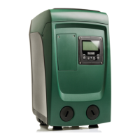
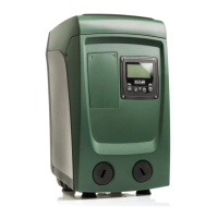
1.1 Description of the Integrated Inverter 65
1.2 Integrated expansion vessel 65
1.3 Integrated electropump 66
1.4 Technical characteristics 67
2. Installation 68
2.1 9HUWLFDO&RQ¿JXUDWLRQ 68
2.1.1 Hydraulic connections 69
2.1.2 Loading operation – Installation above head and below head 70
2.2 +RUL]RQWDOFRQ¿JXUDWLRQ 70
2.2.1 Hydraulic connections 70
2.2.2 Orientation of the interface panel 71
2.2.3 Loading operation – Installation above head and below head 72
3. Commissioning 72
3.1 Electrical connections 72
3.2 &RQ¿JXUDWLRQRIWKHLQWHJUDWHGLQYHUWHU 72
3.3 Priming 72
4. Protection systems 74
4.1 Description of blockages 74
4.1.1 “BL” AAnti Dry-Run (Protection against dry running) 74
4.1.2 Anti-Cycling (Protection against continuous cycles without utility request) 74
4.1.3 Anti-Freeze (Protection against freezing of water in the system) 74
4.1.4 “BP1” Blockage due to fault of the internal pressure sensor 75
4.1.5 “BP2” Blockage due to reading error on the remote pressure sensor 75
4.1.63%´%ORFNDJHGXHWROLQHYROWDJHRXWVLGHVSHFL¿FDWLRQV
4.1.7 “SC” Blockage due to short circuit between the motor phases 75
4.2 Manual reset of error conditions 76
4.3 Self-reset of error conditions 76
5. Inverter electronic control and user interface 76
5.1 Electrical connections of utility inputs and outputs 76
6. The keypad and the display 79
6.1 Direct access with a combination of keys 80
6.2 Access by name with a drop-down menu 84
6.3 Structure of the menu pages 85
6.4 Blocking parameter setting by Password 86
6.5 Enabling and disabling the motor 86
7. Meaning of the individual parameters 86
7.1 User Menu 86
7.1.1 Status 87
7.1.2 RS: Rotation speed display 87
7.1.3 VP: Pressure display 87
7.1.4 VF: Flow display 87
7.1.5 PO: Absorbed power display 87
7.1.6 C1: Phase current display 87
7.1.7 Operating hours and number of starts 87
7.1.8 Multi-pump system 87
7.1.9 VE: Version display 87
7.1.10 PI: Power histogram 88
7.1.11 FF: Fault log display 88
7.2 Monitor Menu 88
7.2.1 CT: Display contrast 88
7.2.2 BK: Display brightness 88
7.2.3 TK: Backlight switch-on time 88
7.2.4 LA: Language 88
7.2.5 TE: Dissipator temperature display 88
7.3 Setpoint Menu 88
7.3.1 SP: Setting the setpoint pressure 89
7.3.2 Setting the auxiliary pressures 89
7.3.2.1 P1: Setting the auxiliary setpoint 1 89
7.3.2.2 P2: Setting the auxiliary setpoint 2 89
7.3.2.3 P3: Setting the auxiliary setpoint 3 89
7.3.2.4 P4: Setting the auxiliary setpoint 4 89
7.4 Manual Menu 89
7.4.1 Status 90
7.4.2 RI: Speed setting 90
7.4.3 VP: Pressure display 90
7.4.4 VF: Flow display 90
7.4.5 PO: Absorbed power display 90
7.4.6 C1: Phase current display 90
7.4.7 RS: Rotation speed display 90
7.4.8 TE: Dissipator temperature display 90
7.5 Installer Menu 90
7.5.1 RP: Setting the pressure fall to restart 90
7.5.2 OD: Type of plant 90
$'$GGUHVVFRQ¿JXUDWLRQ 91
7.5.4 MS: Measuring system 91
7.5.5 AS: Association of devices 91
7.5.6 PR: Remote pressure sensor 92
7.6 Technical Assistance Menu 92
7.6.1 TB: Water lack blockage time 92
 Loading...