ENGLISH
GB
76
4.3 - Self-reset of error conditions
For some malfunctions and blockage conditions, the system attempts
automatic self-reset.
The auto self-reset procedure concerns in particular:
“BL” Blockage due to water lack
³3%´ %ORFNDJHGXHWROLQHYROWDJHRXWVLGHVSHFL¿FDWLRQV
“OT” Blockage due to overheating of the power stages
“OC” Blockage due to motor overload
“BP” Blockage due to fault of the pressure sensor
For example, if the system is blocked due to water lack, the device auto-
matically starts a test procedure to check whether the machine is really
OHIWGH¿QLWLYHO\DQGSHUPDQHQWO\GU\,IGXULQJWKHVHTXHQFHRIRSHUDWLRQV
an attempted reset is successful (for example, the water comes back),
the procedure is interrupted and normal operation is resumed.
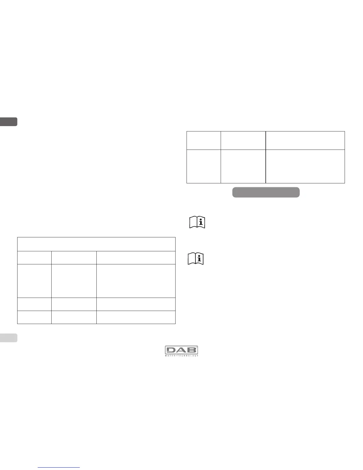
Table 21 shows the sequences of the operations performed by the device
for the different types of blockage.
Automatic resets of error conditions
Display indica-
tion
Description Automatic reset sequence
BL
Blockage due to water
lack
- One attempt every 10 minutes for a
total of 6 attempts
- One attempt every hour for a total of
24 attempts
- One attempt every 24 hours for a total
of 30 attempts
LP
Blockage due to low
supply voltage
,WLVUHVHWZKHQLWUHWXUQVWRDVSHFL¿F
voltage
HP
Blockage due to high
internal supply voltage
,WLVUHVHWZKHQLWUHWXUQVWRDVSHFL¿F
voltage
OT
Blockage due to over-
heating of the power
stages
-It is reset when the temperature of
the power stages returns within the
VSHFL¿FDWLRQV
OC
Blockage due to motor
overload
- One attempt every 10 minutes for a
total of 6 attempts
- One attempt every hour for a total of
24 attempts
- One attempt every 24 hours for a total
of 30 attempts
5 - INVERTER ELECTRONIC CONTROL AND USER INTERFACE
The inverter makes the system work at constant pressure. This
regulation is appreciated if the hydraulic plant downstream from
the system is suitably sized. Plants made with pipes with too
small a section introduce load losses that the equipment cannot
compensate; the result is that the pressure is constant on the
sensors but not on the utility.
Plants that are excessively deformable can create the onset
of oscillations; if this occurs, the problem can be solved by
adjusting the control parameters “GP” and “GI” (see par 7.6.4 -
*33URSRUWLRQDOJDLQFRHI¿FLHQWDQG*,,QWHJUDOJDLQ
FRHI¿FLHQW
5.1 - Electrical connections of utility inputs and outputs
The device can be connected to other devices by means of the propri-
etary wireless channel. One of these devices is the input output control
unit.
Some of the functions that it possesses are the 6 optoinsulated and 2 non
optoinsulated digital inputs and the 8 outputs, also insulated.
The device connects to 4 of these inputs and 2 of the outputs so as to
create interface solutions with more complex installations.
6KRZQLQ)LJXUHDQG)LJXUHIRUH[DPSOHDUHWZRSRVVLEOHFRQ¿JXUD-
tions of the inputs and outputs.
Table 3: Self-reset of blockages
 Loading...