71
71
with the aid of the accessory tool or with a screwdriver.
Make the connection at output from the system through the mouth on Face C
marked “OUT 1” in Fig.10 and/or through the mouth on Face D marked “OUT
´LQ)LJGHOLYHU\FRQQHFWLRQ,QWKLVFRQ¿JXUDWLRQHLWKHURIWKHPRXWKV
can be used as an alternative to the other (depending on the convenience
of the installation), or simultaneously (dual delivery system). So remove the
cap(s) from the door(s) you intend to use with the aid of the accessory tool or
with a screwdriver.
All the hydraulic connections of the system to the plant to which it can be con-
nected are of the threaded female type 1” GAS, made of brass.
See WARNING for Figure 9.
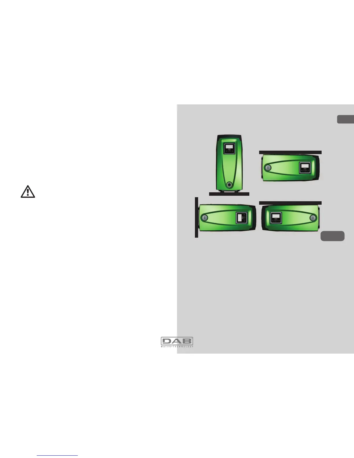
2.2.2 Orientation of the Interface Panel
The Interface Panel has been designed so that it can be oriented in
the direction where it is most convenient for the user to read: its square
shape allows it to be rotated from 90° to 90° (Fig.11).
Figure 11
'LVHQJDJHWKHVFUHZVDWWKHFRUQHUVRIWKHSDQHOXVLQJWKH
hex wrench provided with the accessory tool.
'RQRWUHPRYHWKHVFUHZVMXVWGLVHQJDJHWKHPIURPWKHWKUHDG
on the product body.
%HFDUHIXOQRWWRGURSWKHVFUHZVLQWRWKHV\VWHP
0RYHWKHSDQHODZD\WDNLQJFDUHQRWWRSXOORQWKHVLJQDO
transmission cable
5HSRVLWLRQWKHSDQHOLQLWVVHDWDWWKHSUHIHUUHGDQJOHWDNLQJ
care not to pinch the cable.
7LJKWHQWKHVFUHZVZLWKWKHZUHQFK
ENGLISH
GB

 Loading...