1,2,3,4,5,6,
7,8,9,10,11,
,
,
,
,
ALARM 1 to ALARM 16. The alarm becomes active in low voltage.
1-ON C,2-ON C,
3-ON C,4-ON C,
5-ON C,6-ON C,
,
Eight groups of normal open activation output (on/off button)
A/B The A/B cable to control the RS485 devices. It is to connect to
control devices such as PTZ dome camera. 120Ω should be parallel
connected between A, B lines on the far end to reduce reflection and
guarantee the signal quality.
Tx and Rx RS232 port. Tx is the data output cable and the Rx is the data input
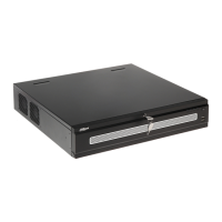
2.3.1.2 NVR608--4K Series
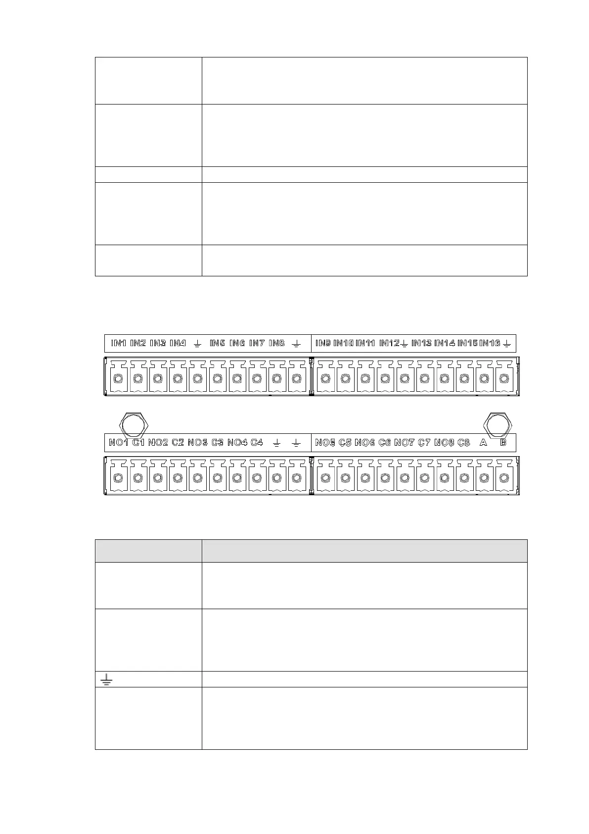
You can refer to the following sheet for alarm input and output information. See Figure 2-18.
Figure 2-18
Icon Note
1,2,3,4,5,6,
7,8,9,10,11,
12,13,14,15,16
ALARM 1 to ALARM 16. The alarm becomes active in low voltage.
1-ON C,2-ON C,
3-ON C,4-ON C,
5-ON C,6-ON C,
7-ON C,8-ON C
Eight groups of normal open activation output (on/off button)
A/B The A/B cable to control the RS485 devices. It is to connect to
control devices such as PTZ dome camera. 120Ω should be parallel
connected between A, B lines on the far end to reduce reflection and
guarantee the signal quality.
24
 Loading...