Check SiUS091601EA
189 Part 6 Service Diagnosis
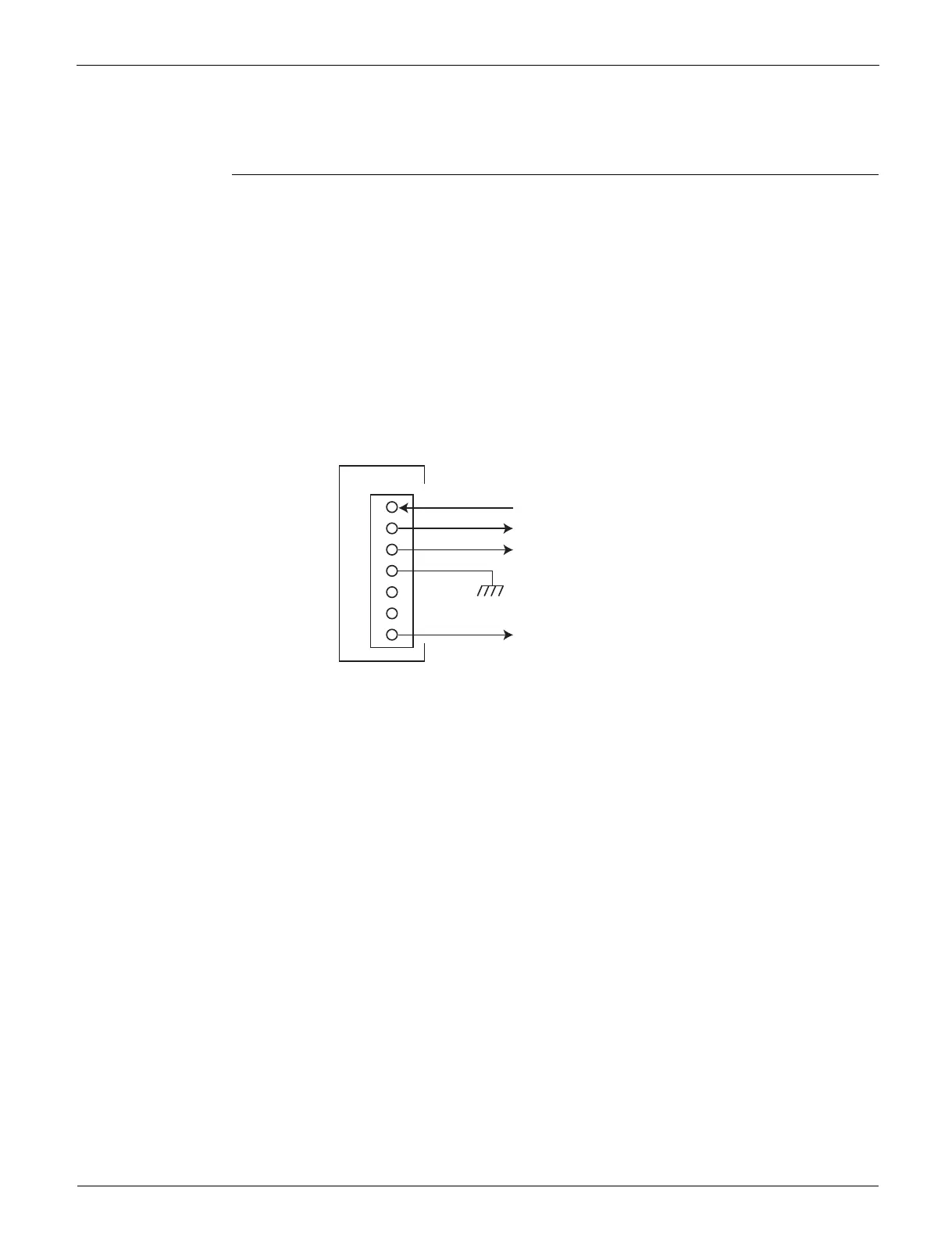
8.8 Rotation Pulse Check on the Outdoor Unit PCB
Check No.16 Make sure that the voltage is within 320 VDC.
1. Set operation off and power off. Disconnect the connector S70 or S71.
2. Check that the voltage between the pins 4 - 7 is 320 VDC.
3. Check that the control voltage between the pins 4 - 3 is 15 VDC.
4. Check that the rotation command voltage between the pins 4 - 2 is 0 ~ 6.5 VDC.
5. Keep operation off and power off. Connect the connector S70 or S71.
6. Check whether 4 rotation pulses (0 ~ 15 VDC) are input at the pins 4 - 1 when the fan motor is
rotated 1 turn by hand.
When the fuse is melted, check the outdoor fan motor for proper function.
If NG in step 2 Defective PCB Replace the outdoor unit PCB (main PCB).
If NG in step 4 Defective Hall IC Replace the outdoor fan motor.
If OK in both steps 2 and 4 Replace the outdoor unit PCB (main PCB).
1
2
3
4
5
6
7
320 VDC
(R20507)
S70 or S71
PCB
Actual rotation pulse input (0 ~ 15 VDC)
Rotation command voltage (0 ~ 6.5 VDC)
Control voltage 15 VDC
 Loading...