VLT is a registered Danfoss trademark
1-3
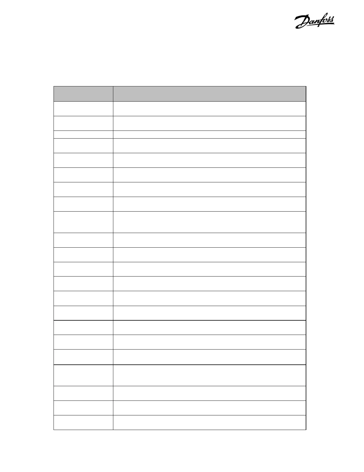
Table 1-1. VLT 5000 Series Status Definitions
Table 1-1 defines the status line display shown in VLT 5000
series drives.
DISPLAY DESCRIPTION
AUTO MOTOR
ADAPT
Automatic motor adaptation enabled in parameter 107, Automatic
Motor Adaptation, AMA and drive performing adaptation function.
BRAKE CHECK OK Brake check function is completed and brake resistor and transistor
tested successfully.
BRAKING Drive brake is functioning and motor is being slowed.
BRAKING MAX Drive brake functioning at maximum. Drive brakes to its maximum
when running 100% duty cycle.
CATCH UP Drive output frequency increased by percentage value selected in
parameter 219, Catch up/Slow down Value.
CONTROL READY Condition causing UNIT NOT READY status has been rectified and
drive is ready for operation.
CURRENT HIGH Warning of drive output current higher than value set in parameter
224, Warning: High Current. Drive will continue to operate.
CURRENT LOW Warning of drive output current lower than value set in parameter 223,
Warning: Low Current. Drive will continue to operate.
EXCEPTIONS
XXXX
Control microprocessor stopped for unknown cause and drive not
operating. Cause may be due to noise on the power line, motor leads
or control wires.
FEEDBACK HIGH Warning of a feedback signal higher than value set in parameter 228,
Warning: High Feedback. Drive will continue to operate.
FEEDBACK LOW Warning of a feedback signal lower than value set in parameter 227,
Warning: Low Feedback. Drive will continue to operate.
FREEZE OUTPUT Drive output frequency frozen at current rate via digital input or serial
communication.
FREQUENCY
HIGH
Warning of drive frequency higher than value set in parameter 226,
Warning: High Frequency. Drive will continue to operate.
FREQUENCY LOW Warning of drive frequency lower than value set in parameter 225,
Warning: Low Frequency. Drive will continue to operate.
LOCAL/DC STOP Local control selected and drive stopped via a DC braking signal on
terminal 27 or serial communication.
LOCAL/LCP STOP Local control selected and drive is stopped via control panel. Coast
signal on terminal 27 high.
LOCAL/QSTOP Local control selected and drive stopped via a quick-stop signal on
terminal 27 or serial communication.
LOCAL/RAMPING Local control selected and motor speed and drive output frequency is
changing.
LOCAL/RUN JOG Local control selected and drive is running at a fixed frequency set in
parameter 213, Jog Frequency via digital input or serial
communication.
LOCAL/RUN OK Local control selected and motor is running and speed corresponds to
reference.
LOCAL/STOP Local control selected and drive stopped via control panel, digital input
or serial communication.
LOCAL/UNIT
READY
Local control selected and 0 V on terminal 27.
 Loading...
