1-4
VLT is a registered Danfoss trademark
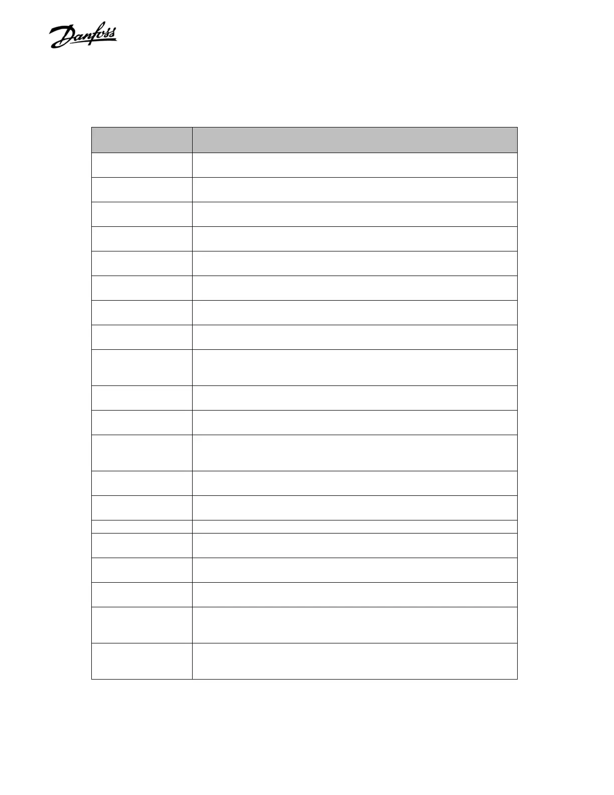
Table 1-1. VLT 5000 Series Status Definitions (continued)
DISPLAY DESCRIPTION
OFF1 Stop command (Ramp Down) received via serial communication, and
Fieldbus selected in parameter 512.
OFF2 Stop command (Coast) received via serial communication, and
Fieldbus selected in parameter 512.
OFF3 Stop command (Q Stop) received via serial communication, and
Fieldbus selected in parameter 512.
OVER VOLTAGE
CONTROL
Parameter 400,
Overvoltage Control
, enabled. Drive is attempting to
avoid a trip from overvoltage by extending decel ramp time.
QUICK
DISCHARGE OK
Quick discharge function has been completed successfully.
REM/BUS JOG1 Remote control selected and Fieldbus selected in parameter 512. Jog
1 command has been given via serial communication.
REM/BUS JOG2 Remote control selected and Fieldbus selected in parameter 512. Jog
2 command has been given via serial communication.
REM/DC STOP Remote control selected and drive stopped via a DC stop signal on a
digital input or serial communication.
REM/LCP STOP Remote control selected and drive is stopped via control panel. Coast
signal on terminal 27 high. Start command via remote digital input or
serial communication is overridden.
REM/QSTOP Remote control selected and drive stopped via a quick-stop signal on
terminal 27 or serial communication.
REM/RAMPING Remote control selected and motor speed and drive output frequency
is changing.
REM/RUN JOG Remote control selected and drive is running at a fixed frequency set
in parameter 213,
Jog Frequency
via digital input or serial
communication.
REM/RUN OK Remote control selected and motor is running and speed corresponds
to reference.
REM/STOP Remote control selected and drive stopped via control panel, digital
input or serial communication.
REM/UNIT READY Remote control selected and 0 V on terminal 27.
SLOW DOWN Drive output frequency reduced by percentage value selected in
parameter 219,
Catch up/Slow down Value
.
STAND BY Drive will start when a start signal received via digital input or serial
communication.
START
FORW./REV
Input on digital inputs and parameter data are in conflict.
START INHIBIT OFF1, OFF2, OFF3 condition has been rectified. Drive cannot start
until OFF1 bit is toggled (OFF1 set from 1 to 0 then to 1). Fieldbus
selected in parameter 512.
UNIT NOT READY Drive not ready for operation because of a trip or because OFF1,
OFF2 or OFF3 is a logic ‘0.’ (Only on units with external 24 VDC
supply.)
 Loading...
