8.5.10 IGBT Switching Test
WARNING
DISCHARGE TIME
The drive contains DC-link capacitors, which can remain
charged even when the drive is not powered. High
voltage can be present even when the warning LED
indicator lights are o. Failure to wait the specied time
after power has been removed before performing service
or repair work can result in death or serious injury.
•
Stop the motor.
•
Disconnect AC mains and remote DC-link power
supplies, including battery back-ups, UPS, and
DC-link connections to other drives.
•
Disconnect or lock the motor.
•
Disconnect any brake option.
•
Disconnect any regen/load share option.
•
Wait for the capacitors to discharge fully. The
minimum waiting time is specied in the
following discharge time table and is also
visible on the drive label.
•
Before performing any service or repair work,
use an appropriate voltage measuring device to
make sure that the capacitors are fully
discharged. For parallel drive modules, measure
DC-bus capacitor voltages before and after the
individual DC fuses.
Enclosure Size Minimum waiting time
D1h–D8h drives 20 minutes
J8–J9 drives 20 minutes
D9h–D10h enclosed drive systems 20 minutes
Da2/Da4/Db2/Db4 parallel drive systems 20 minutes
E1h–E4h drives 40 minutes
E5h–E6h enclosed drive systems 40 minutes
Table 8.6 Discharge Time
To determine whether the IGBTs are switching correctly,
use the following procedure.
1. Connect the split bus power supply. See
chapter 9.1.1 Overview.
2. Switch on the 650 V DC supply and 24 V DC
supply.
3. Apply a run command and speed command of
approximately 40 Hz.
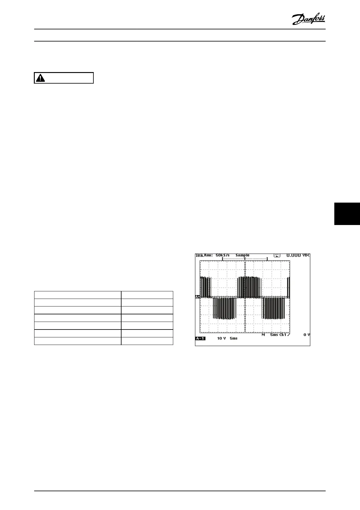
4. Measure the phase-to-phase output waveform on
all 3 output phases of the drive using an
oscilloscope (preferred) or a voltmeter.
4a When measuring with an oscilloscope,
the waveform appears the same as in
normal operation, except that the
amplitude is 24 V peak. See
Illustration 8.15
4b When measuring with a voltmeter set to
read AC voltage, the meter reads
approximately 17 V AC on all 3 phases.
Dierences in drive settings can cause a
slight variation in this reading, but it is
important that the readings are equal
on all 3 phases.
Illustration 8.15 Output Wave Form
An incorrect reading indicates either a defective IGBT or
gate drive signal. To determine if the gate drive signal is
correct, perform the gate drive signal test. See
chapter 8.5.11 IGBT Gate Drive Signals Test.
Test Procedures Service Guide
MG94A502 Danfoss A/S © 02/2019 All rights reserved. 111
8 8
 Loading...


