13.2.19 DC Snubber Capacitors
To remove or reinstall the DC snubber capacitors, select either the following procedure for E1h/E3h drives or the procedure
for E2h/E4h drives.
Disassembly in E1h/E3h drives
In E1h/E3h drives, the DC snubber capacitors are located
along the top of the DC capacitor plates. Refer to
Illustration 13.18.
1. Remove the input plate. Refer to
chapter 13.2.9 Input Plate with Busbars and
chapter 13.2.10 Split Input Plate with Options.
2. Remove the gate drive card mounting plate. Refer
to chapter 13.2.13 Gate Drive Card Mounting Plate.
3. Remove 3 nuts (13 mm), 1 from the top of each
current sensor busbar.
4. Remove 3 screws (T25), 1 from the middle of
each IGBT output busbar.
5. Remove 6 nuts (13 mm), 2 from the top of each
IGBT output busbar. Lift the 3 IGBT output
busbars from the drive.
6. Remove 12 screws (T30), 2 from the bottom of
each DC snubber capacitor.
7. Remove the 6 DC snubber capacitors from the
drive.
Reassembly in E1h/E3h drives
Tighten fasteners according to chapter 14.1 Fastener Torque
Ratings.
1. Position the DC snubber capacitors in the drive.
2. Secure 12 screws (T30), 2 at the bottom of each
DC snubber capacitor.
3. Position the IGBT output busbars in the drive.
Secure 6 nuts (13 mm), 2 at the top of each IGBT
output busbar.
4. Replace 3 screws (T25), 1 in the middle of each
IGBT output busbar.
5. Secure 3 nuts (13 mm) 1 at the top of each
current sensor busbar.
6. Replace the gate drive card mounting plate. Refer
to chapter 13.2.13 Gate Drive Card Mounting Plate.
7. Replace the input plate. Refer to
chapter 13.2.9 Input Plate with Busbars and
chapter 13.2.10 Split Input Plate with Options.
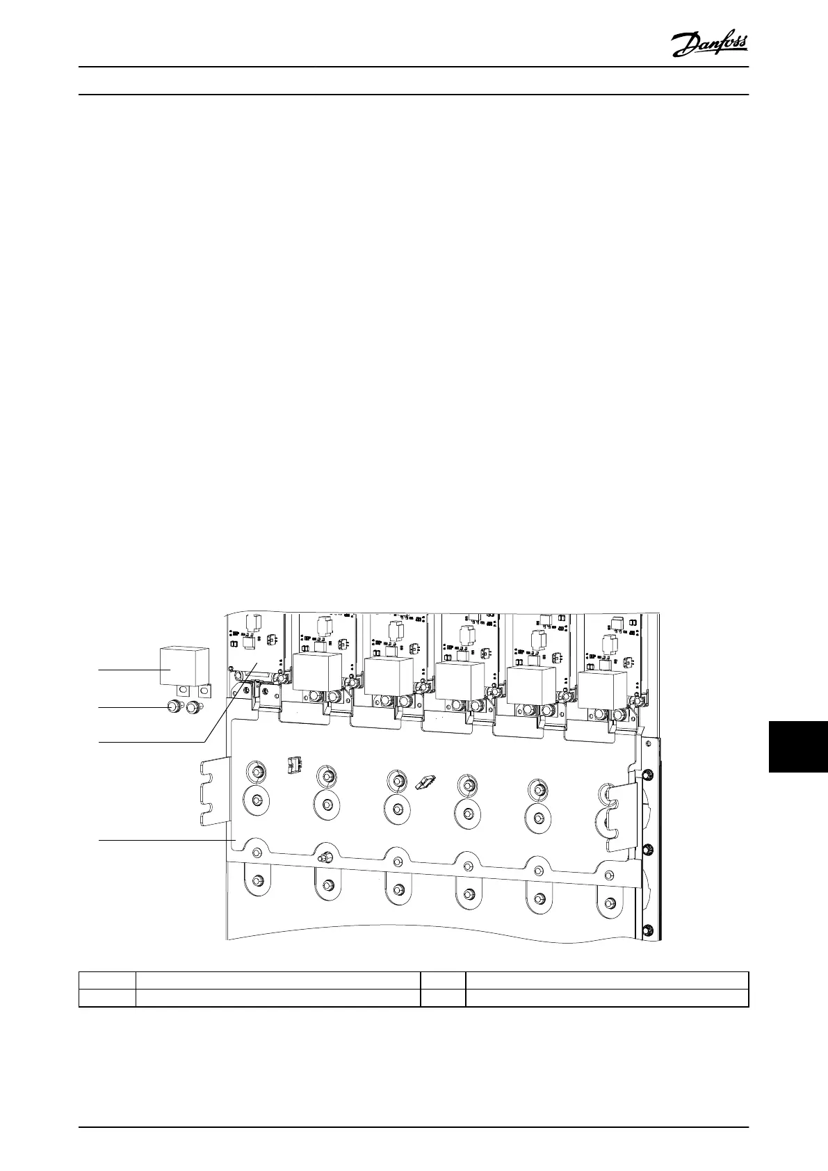
1 DC snubber capacitor 3 IGBT module
2 Screw (T30) 4 DC bus plates
Illustration 13.18 DC Snubber Capacitors in E1h/E3h Drives
E1h–E4h Drive Disassembly a... Service Guide
MG94A502 Danfoss A/S © 02/2019 All rights reserved. 295
13 13
 Loading...


