4.3 Status Messages
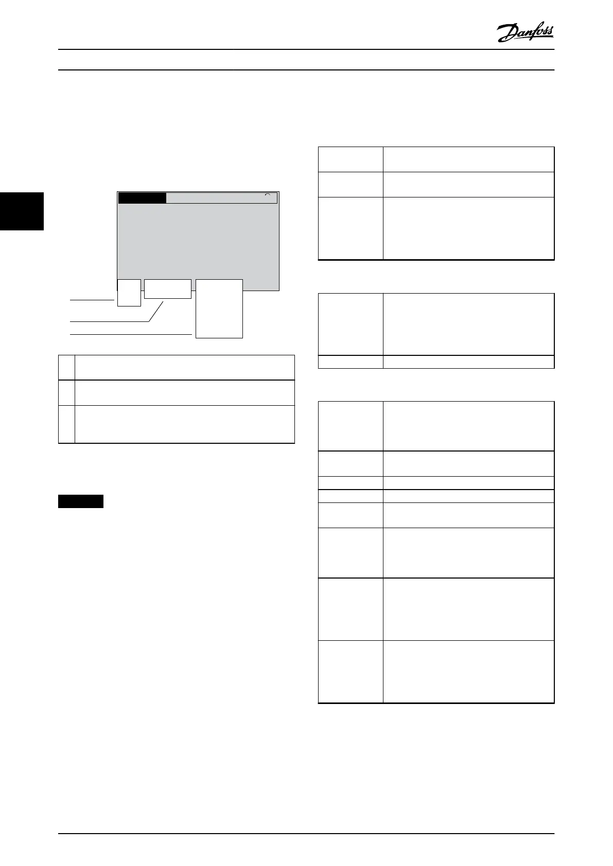
When the drive is in status mode, status messages
automatically appear in the bottom line of the LCP display
(refer to Illustration 4.4.) Status messages are dened in
Table 4.10 – Table 4.12.
Status
799RPM 7.83A 36.4kW
0.000
53.2%
1(1)
Auto
Hand
O
Remote
Local
Ramping
Stop
Running
Jogging
.
.
.
Stand-by
130BB037.11
1
2
3
1 The rst part of the status line indicates where the stop/
start command originates. Refer to Table 4.10.
2 The second part of the status line indicates where the
speed control originates. Refer to Table 4.11.
3 The last part of the status line gives the present drive
status. The status shows the operational mode that the
drive is in. Refer to Table 4.12.
Illustration 4.4 Status Display
NOTICE
AUTO/REMOTE MODE
In auto/remote mode, the drive requires external
commands to execute functions.
4.4 Status Message Denitions
Table 4.10 – Table 4.12 dene the listed status messages.
O The drive does not react to any control signal
until [Auto On] or [Hand On] is pressed.
Auto Start/stop commands are sent via the control
terminals and/or serial communication.
Hand The navigation keys on the LCP can be used
to control the drive. Stop commands, reset,
reversing, DC brake, and other signals applied
to the control terminals can override local
control.
Table 4.10 Operating Mode
Remote The speed reference is given from
•
External signals.
•
Serial communication.
•
Internal preset references.
Local The drive uses reference values from the LCP.
Table 4.11 Reference Site
AC braking AC braking was selected in
parameter 2-10 Brake Function. The AC braking
overmagnetizes the motor to achieve a
controlled slow down.
AMA nish OK Automatic motor adaptation (AMA) was
carried out successfully.
AMA ready AMA is ready to start. Press [Hand On].
AMA running AMA process is in progress.
Braking The brake chopper is in operation. The brake
resistor absorbs the generative energy.
Braking max. The brake chopper is in operation. The power
limit for the brake resistor dened in
parameter 2-12 Brake Power Limit (kW) has
been reached.
Bus jog 1 PROFIdrive prole was selected in
parameter 8-10 Control Prole. The Jog 1
function is activated via serial communication.
The motor is running with parameter 8-90 Bus
Jog 1 Speed.
Bus jog 2 PROFIdrive prole was selected in
parameter 8-10 Control Prole. The Jog 2
function is activated via serial communication.
The motor is running with parameter 8-91 Bus
Jog 2 Speed.
Operator Interface and Driv...
VLT
®
FC Series, D1h–D8h, Da2/Db2/Da4/Db4, E1h–E4h, J8/J9
34 Danfoss A/S © 02/2019 All rights reserved. MG94A502
44
 Loading...


