12.2.3 Installing the Drive Modules
Install the drive modules into the cabinet enclosure as described in the following steps.
1. Unpack the drive modules from the packaging.
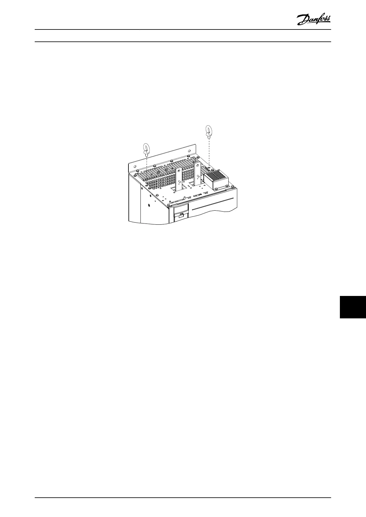
2. Install 2 eye bolts in the top of the rst drive module. Prepare the drive module for lifting, using an appropriate
lifting harness and an overhead hoist or crane with the necessary lifting capacity.
Illustration 12.4 Installation of Eye Bolts
3. Install the 2 bottom screws and gaskets onto the mounting panel.
4. Using the crane or hoist, lift the drive module and then lower the unit through the top of the cabinet enclosure.
Align the bottom mounting holes of the unit with the 2 bottom screws on the mounting panel.
5. Check that the drive module is aligned correctly on the mounting panel. Secure the bottom of the unit to the
panel with 2 nuts. See Illustration 12.3. Torque the hex nuts. Refer to chapter 14.1 Fastener Torque Ratings.
6. Secure the top of the unit to the mounting panel with M10x26 screws, and then torque the screws.
7. Line up the groove on the microswitch with the edges on each DC fuse and press rmly until the microswitch
clicks into place.
8. Install 2 DC fuses onto the tops of the DC-link terminals on each drive module.
9. Install the microswitches on the outer side of each DC-link terminal. Refer to Illustration 3.7.
10. Secure each fuse with 2 M10 screws and torque the screws.
11. Install the next drive module.
Da2/Db2/Da4/Db4 Parallel Sy... Service Guide
MG94A502 Danfoss A/S © 02/2019 All rights reserved. 251
12 12
 Loading...


