9.3.2 Signal Test Board Pin Outs
Table 9.2 lists the pins found on the signal test board. For each pin, its function, description, and voltage levels are provided.
Details on performing tests using the test xture are provided in chapter 8 Test Procedures of this guide. Other than power
supply measurements, most of the signals being measured are made up of waveforms.
Sometimes, a digital voltmeter can be used to verify the presence of such signals. However, do not rely on the voltmeter to
verify that the waveform is correct. An oscilloscope is the preferred instrument. When similar signals are being measured at
multiple points, a digital voltmeter can be used with some accuracy. By comparing signals to one another, such as gate
drive signals, and obtaining similar readings, it can be concluded that the waveforms match and are correct. Values are
provided for using a digital voltmeter for testing as well.
Pin
No.
Schematic
acronym
Function Description Reading using a
digital voltmeter
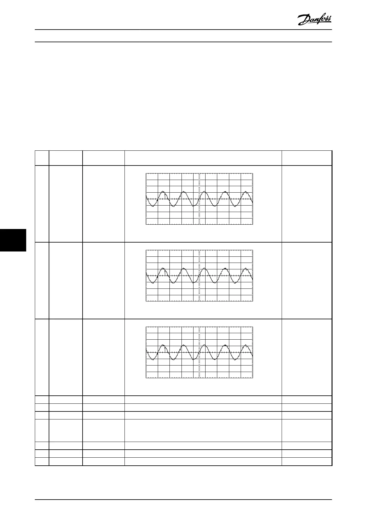
1 IU1 Current sensed,
U phase, not
conditioned
2000.0
1500.0
1000.0
500.0
0.0 mV
-500.0
-1000.0
-1500.0
-2000.0
-200 ms 1 ms/Div
Input A
130BX148.10
Approximately 400 mV RMS at 100% load.
0.937 V AC
peak
at
165% of CT current
rating. AC waveform
at output frequency
of the lter.
2 IV1 Current sensed,
V phase, not
conditioned
2000.0
1500.0
1000.0
500.0
0.0 mV
-500.0
-1000.0
-1500.0
-2000.0
-200 ms 1 ms/Div
Input A
130BX148.10
Approximately 400 mV RMS at 100% load.
0.937 V AC
peak
at
165% of CT current
rating. AC waveform
at output frequency
of the lter.
3 IW1 Current sensed,
W phase, not
conditioned
2000.0
1500.0
1000.0
500.0
0.0 mV
-500.0
-1000.0
-1500.0
-2000.0
-200 ms 1 ms/Div
Input A
130BX148.10
Approximately 400 mV RMS at 100% load.
0.937 VAC
peak
at 165%
of CT current rating.
AC waveform at
output frequency of
the lter.
4 COMMON Logic common This common is for all signals.
5 Not used
6 Not used
7 INRUSH Control card
signal
Signal from the control card to start gating the SCR front end. Signal
not relevant in E1h–E4h drives.
3.3 V DC – Inrush
mode
0 V DC – Run mode
8 Not used
9 Not used
10 Not used
Special Test Equipment
VLT
®
FC Series, D1h–D8h, Da2/Db2/Da4/Db4, E1h–E4h, J8/J9
126 Danfoss A/S © 02/2019 All rights reserved. MG94A502
99
 Loading...


