-
8.1.7 Wiring Conguration: External Alarm Reset
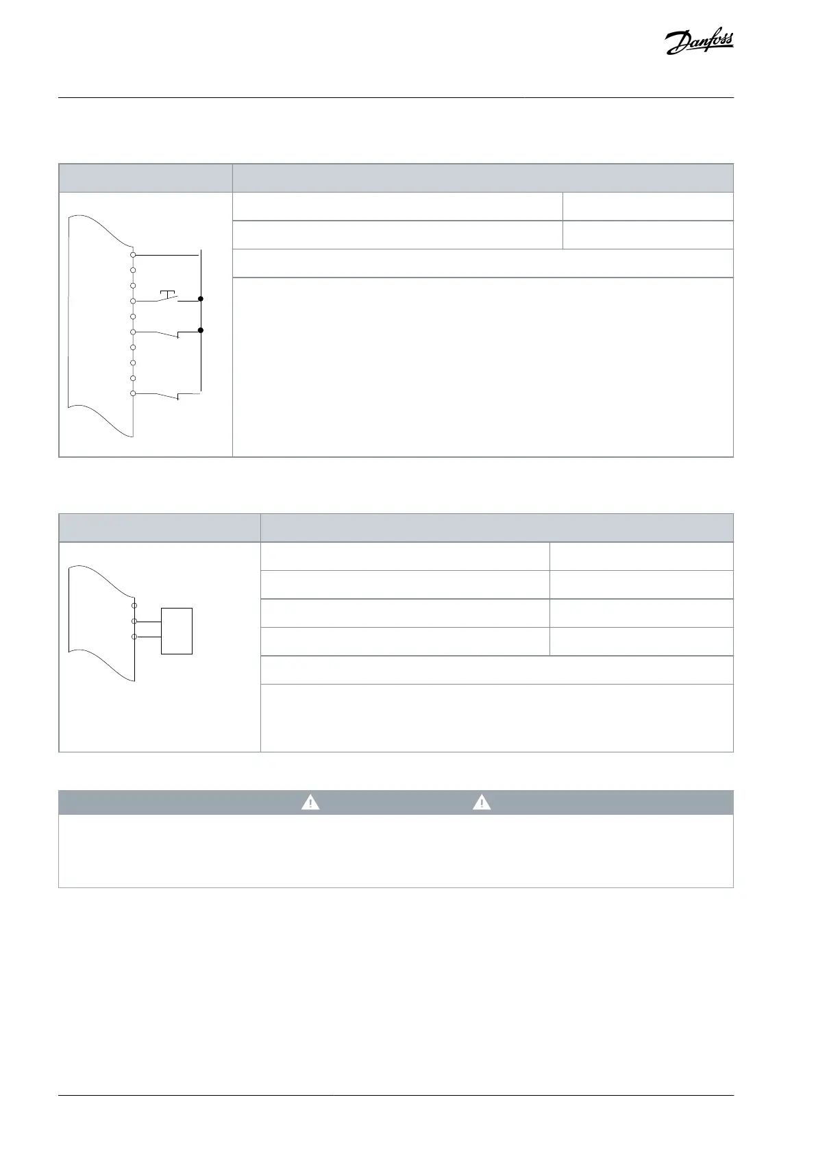
Table 85: Wiring Conguration for External Alarm Reset
+24 V
D IN
D IN
D IN
COM
D IN
D IN
D IN
D IN
e30bu088.10
XD2.13
XD2.18
XD2.14
XD2.15
XD2.16
XD2.17
XD2.19
Parameter 5-11 Terminal 19 Digital Input
Notes/comments:
D IN 37 is an option.
Terminal 19 in the parameter title corresponds to terminal XD2.13 in the control compartment.
8.1.8 Wiring Conguration: RS485
Table 86: Wiring Conguration for RS485 Network Connection
e30bu089.10
XD2.10
XD2.11
XD2.12
-
Notes/comments:
Select protocol, address, and baud rate in the above-mentioned parameters.
D IN 37 is an option.
8.1.9 Wiring Conguration: Motor Thermistor
C A U T I O N
THERMISTOR INSULATION
Risk of personal injury or equipment damage.
Use only thermistors with reinforced or double insulation to meet PELV insulation requirements.
AQ357954340588en-000201 / 130R0881112 | Danfoss A/S © 2020.09
Wiring Conguration Examples
VLT® Refrigeration Drive FC 103
Operating Guide
 Loading...


