-
-
Corresponding terminal within the control compartment
5.7.6 Control Compartment Options
5.7.6.1 Auxiliary Supply Terminals
Table 54: Auxiliary Supply Type Codes
230 V AC external + 24 V DC internal
120 V AC external + 24 V DC internal
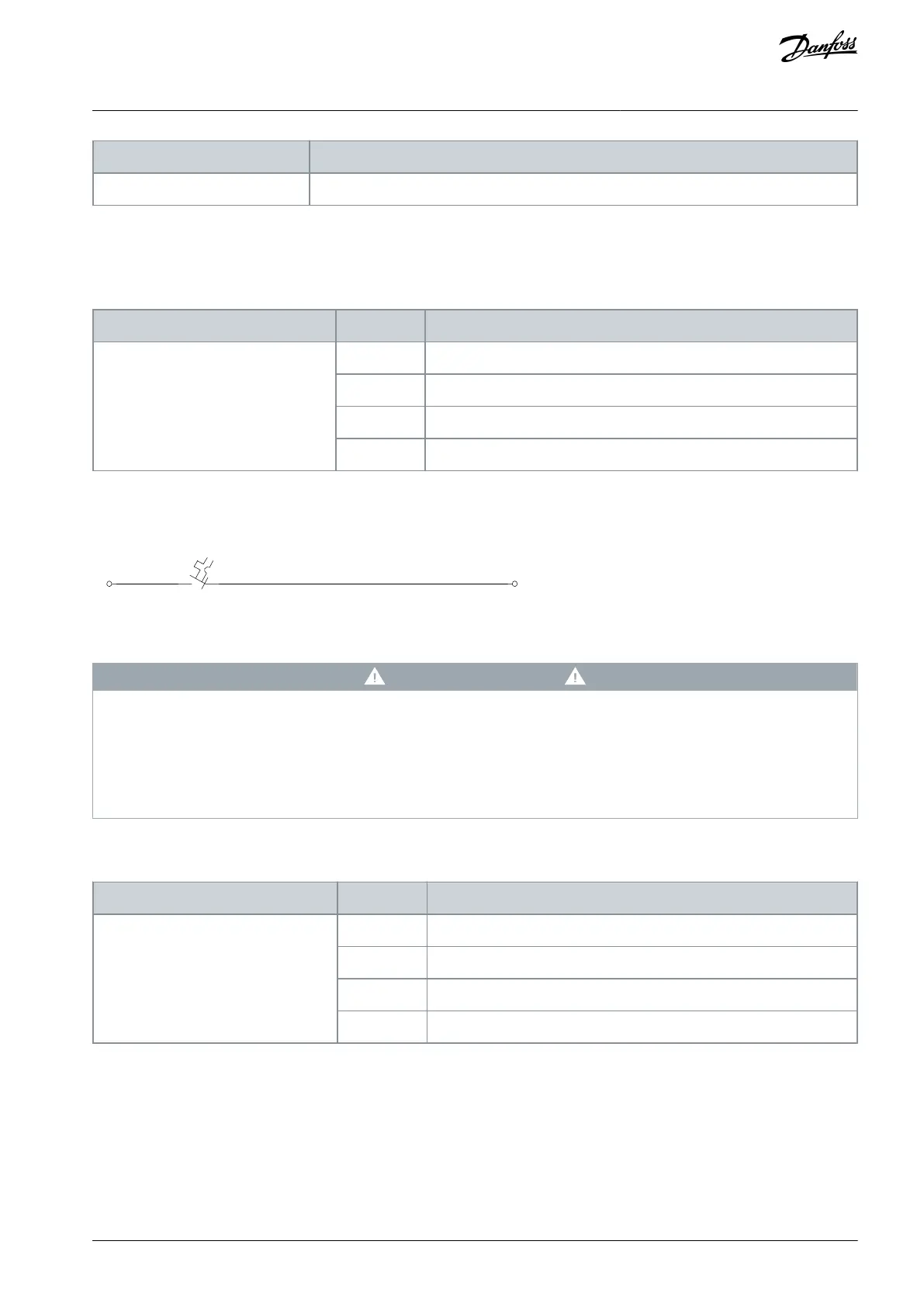
The auxiliary supply terminal option provides an external voltage supply to the –XD1.1 terminal. The external supply must be short-
circuit protected. The power of the external supply depends on other selected cabinet options.
e30bu195.10
-XD1.1
-FC6
-XD1
10 A
2
Illustration 41: Auxiliary AC Supply Terminals
W A R N I N G
HIGH VOLTAGE
The mains disconnect switch does not disconnect the external voltage supply. Failure to disconnect the external voltage supply
before touching any components in the control compartment can result in death or serious injury.
Disconnect the external voltage supply.
Only qualied personnel must install, start up, and maintain the drive.
5.7.6.2 Auxiliary Voltage Transformer
Table 55: Auxiliary Supply Type Codes for Auxiliary Voltage Transformer
230 V AC internal + 24 V DC internal
120 V AC internal + 24 V DC internal
The auxiliary voltage transformer is an option tted internally that allows for the supply to be tapped from the mains. For example, if
the enclosed drive is specied with a fused disconnect, the supply for the auxiliary voltage transformer is taken from between the
drive and the fused disconnect. This conguration allows the control voltage to be disconnected with the main switch.
The transformer has multiple tappings on the primary side for the standard range of voltages on which the drive operates. The fac-
tory default wiring connects to the highest voltage tapping on the primary side, and the trip settings for the -FC4 terminal is set
accordingly. The customer can change the tapping provided the correct voltage is applied and the thermal magnetic circuit breaker
is set accordingly.
AQ357954340588en-000201 / 130R0881 | 75Danfoss A/S © 2020.09
Electrical Installation
VLT® Refrigeration Drive FC 103
Operating Guide
 Loading...


