•
•
1.
2.
3.
4.
5.
Minimum cable cross-section: 10 mm
2
(6 AWG) (or 2 rated ground wires terminated separately).
Tighten the terminals in accordance with the information provided in 10.11 Fastener Torque Ratings.
EMC-compliant Installation
Refer to the EMC-compliant Installation section.
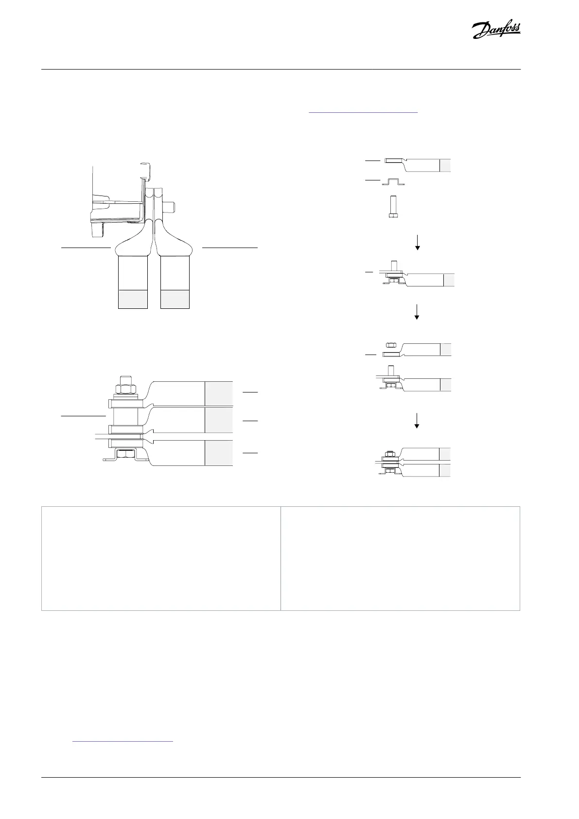
Illustration 47: Dierent Ways of Connecting Multiple Cables to 1 Terminal
Bolt holder on the connector
5.8.2 Connecting to the Mains
If the enclosed drive is not congured with an input lter or input power option, connect the mains to the drive module. Otherwise,
connect the mains to the input power option.
Procedure
Strip a section of the outer cable insulation.
Fasten a connector/cable lug to the end of the stripped cable.
Create an electrical connection between the cable shield and ground by securing the stripped wire under the cable clamp.
Connect the ground wire to the nearest grounding terminal in accordance with the grounding instructions provided in
5.8.6 Connecting to Ground.
Connect the 3-phase AC input power cables to terminals R (L1), S (L2), and T (L3).
AQ357954340588en-000201 / 130R088182 | Danfoss A/S © 2020.09
Electrical Installation
VLT® Refrigeration Drive FC 103
Operating Guide
 Loading...


