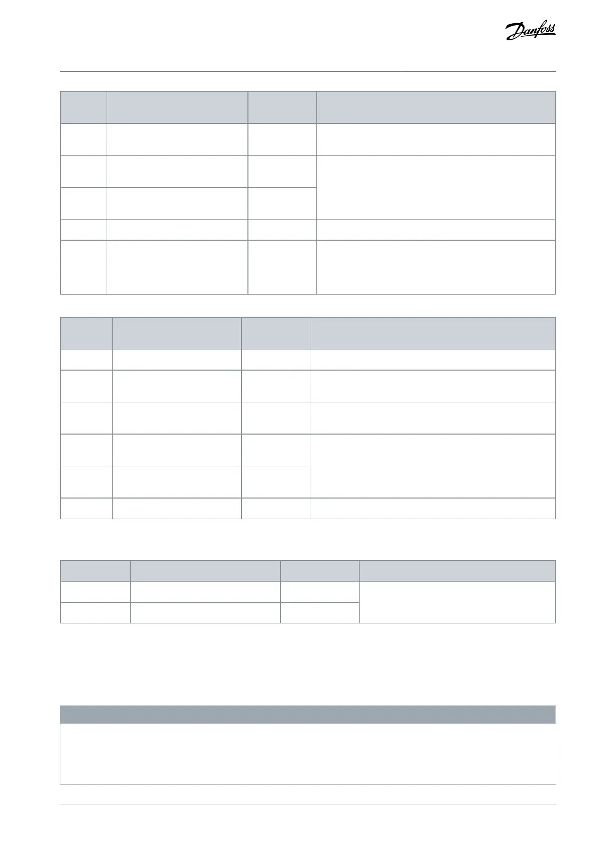
Parameter 5-15 Terminal 33 Digital
Input
Parameter 5-12 Terminal 27 Digital
Input
For digital input or output. Default setting is input.
Parameter 5-13 Terminal 29 Digital
Input
Common for digital inputs and 0 V potential for 24 V supply.
When not using the optional STO feature, a jumper wire is re-
quired between terminal 10 (or 11) and terminal 19. This set-
up allows the drive to operate with factory default program-
ming values.
Table 45: Analog Input/Output Terminal Descriptions
Common for analog output.
Parameter 6-50 Terminal 42 Out-
put
Programmable analog output. 0–20 mA or 4–20 mA at a maxi-
mum of 500 Ω.
10 V DC analog supply voltage for potentiometer or thermis-
tor. 15 mA maximum.
Parameter group 6-1* Analog In-
put 1
Analog input. For voltage (V) or current (mA).
Parameter group 6-2* Analog In-
put 2
5.7.4 Relay Terminals
Table 46: Relay Terminal Descriptions
Parameter 5-40 Function Relay [0]
Form C relay outputs. For AC or DC voltage.
Parameter 5-40 Function Relay [1]
5.7.5 Option Card Terminals
The option cards extend the functionality of drives and provide a high variety of interfaces to automation systems. When the option
cards are specied in the type code, they are mounted in slots A, B, C, and D of the control card within the drive module. The option
card wiring is routed to a terminal block within the control compartment. For more details, refer to the Installation/Operating Guide
for the respective option card.
N O T I C E
OPTION CARD INSTALLATION
If the option card is ordered along with the drive using the type code, the factory installs the option card and its wiring. If the
option is ordered separately, the customer is responsible for installing the option card and the wiring extensions to the control
compartment.
AQ357954340588en-000201 / 130R0881 | 71Danfoss A/S © 2020.09
Electrical Installation
VLT® Refrigeration Drive FC 103
Operating Guide
 Loading...


