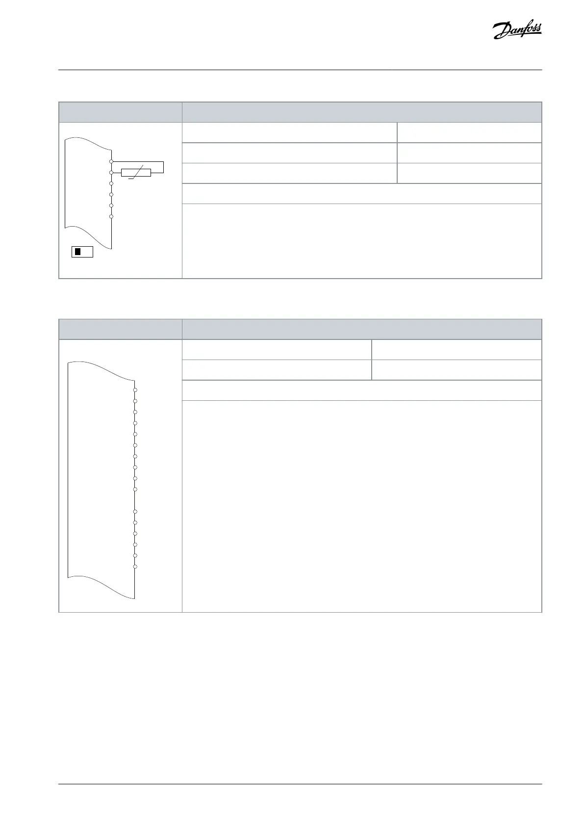
EasyManuals Logo
Home>Danfoss>DC Drives>VLT FC 102 N250

Danfoss VLT FC 102 N250 User Manual

Danfoss VLT FC 102 N250
182 pages
To Next Page IconTo Next Page
To Previous Page IconTo Previous Page
Page #113 background imageLoading...
Page #113 background image
Table 87: Wiring Conguration for Motor Thermistor
Parameters
e30bu090.10
+10 V
A IN
A IN
COM
A OUT
COM
A53
U - I
XD2.6
XD2.7
XD2.8
XD2.9
XD2.5
XD2.4
Function
Setting
Parameter 1-90 Motor Thermal Protection
[2] Thermistor trip
Parameter 1-93 Thermistor Source
[1] Analog input 53
* = Default value
If only a warning is required, set parameter 1-90 Motor Thermal Protection to [1] Thermistor warn-
ing.
D IN 37 is an option.
Input 53 in the parameter corresponds to terminal XD2.7 in the control compartment.
8.1.10 Wiring for Regeneration
Table 88: Wiring Conguration for Regeneration
Parameters
+24 V
+24 V
D IN
D IN
D IN
COM
D IN
D IN
D IN
D IN
+10
V
A IN
A IN
COM
A OUT
COM
XD2.10
XD2.11
XD2.12
XD2.13
XD2.18
XD2.14
XD2.15
XD2.16
XD2.17
XD2.19
XD2.6
XD2.7
XD2.8
XD2.9
XD2.5
XD2.4
e30bu091.10
Function
Setting
Parameter 1-90 Motor Thermal Protection
100%*
* = Default value
To disable regeneration, decrease parameter 1-90 Motor Thermal Protection to 0%. However, if
the application uses motor brake power and regeneration is not enabled, the drive will trip.
AQ357954340588en-000201 / 130R0881 | 113Danfoss A/S © 2020.09
Wiring Conguration Examples
VLT® Refrigeration Drive FC 103
Operating Guide

Table of Contents

Questions and Answers:

Question and Answer IconNeed help?

Do you have a question about the Danfoss VLT FC 102 N250 and is the answer not in the manual?

Danfoss VLT FC 102 N250 Specifications

General IconGeneral
BrandDanfoss
ModelVLT FC 102 N250
CategoryDC Drives
LanguageEnglish

Related product manuals