-
-
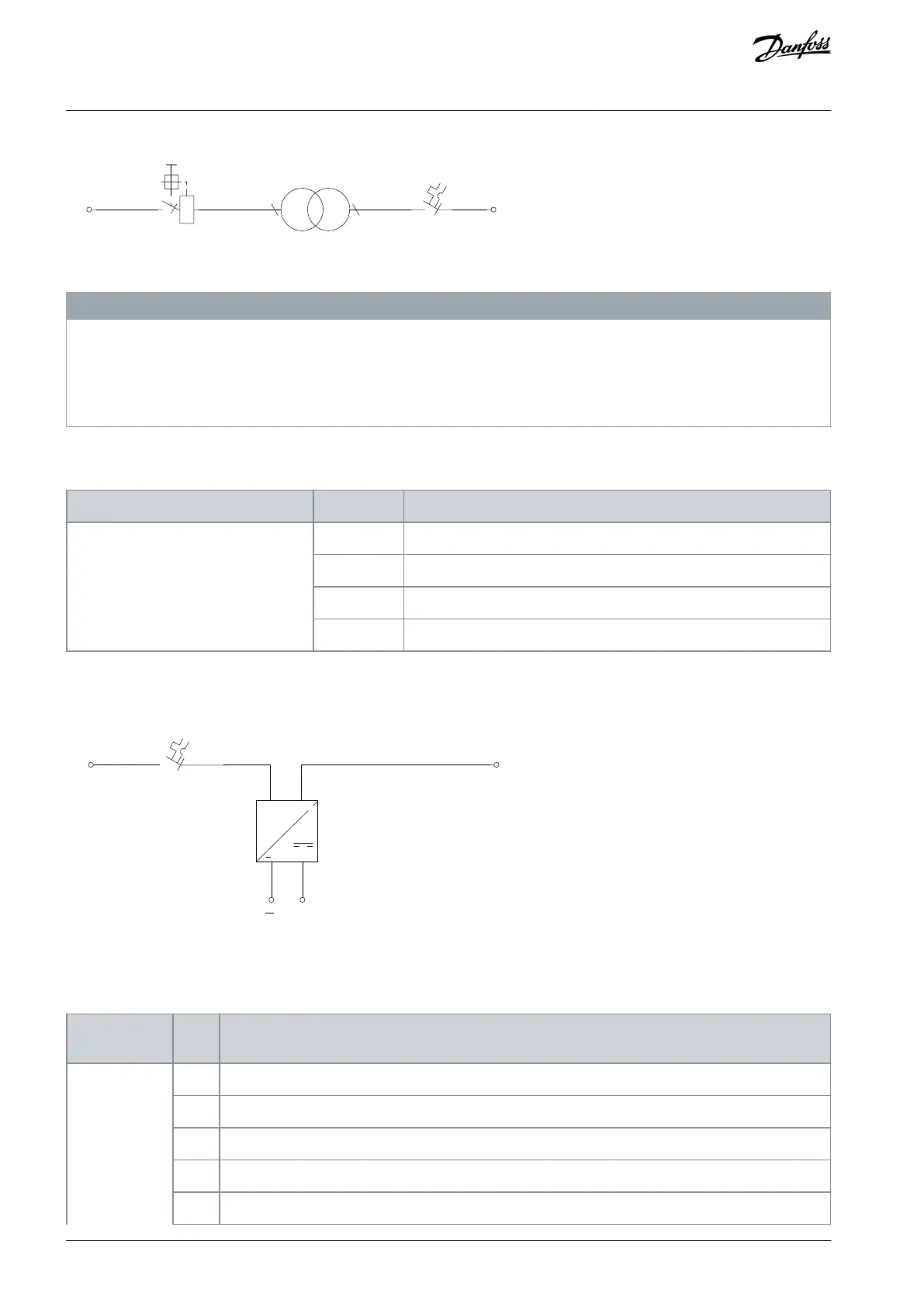
Illustration 42: Auxiliary Voltage Transformer Terminals
N O T I C E
AUXILIARY COMPONENT FAILURE
Incorrect voltage or incorrect tapping installation will cause other auxiliary components in the control compartment to fail.
When tapping the transformer, make sure to apply the correct voltage for the drive.
Use the correct tapping and trip settings.
5.7.6.3 +24 V DC External Supply
Table 56: Auxiliary Supply Type Codes
230 V AC internal+24 V DC internal
230 V AC external+24 V DC internal
120 V AC internal+24 V DC internal
120 V AC external+24 V DC internal
The 24 V DC external supply option enables other auxiliary options to be connected to a 24 V DC supply within the control compart-
ment.
Illustration 43: 24 V DC External Supply Terminals
5.7.6.4 AC Customer Socket
Table 57: Auxiliary Function Type Codes
AC socket + cabinet light
AC socket + cabinet light + extended I/O terminals
AC socket + cabinet light + cabinet heater
AC socket + cabinet light + motor heater control
AC socket + cabinet light + insulation monitor
AQ357954340588en-000201 / 130R088176 | Danfoss A/S © 2020.09
Electrical Installation
VLT® Refrigeration Drive FC 103
Operating Guide
 Loading...


