4.3 Installing the Drive Modules
Install the drive modules into the cabinet frame as described in the following steps.
1. Unpack the drive modules from the packaging. See chapter 4.1 Receiving and Unpacking the Unit.
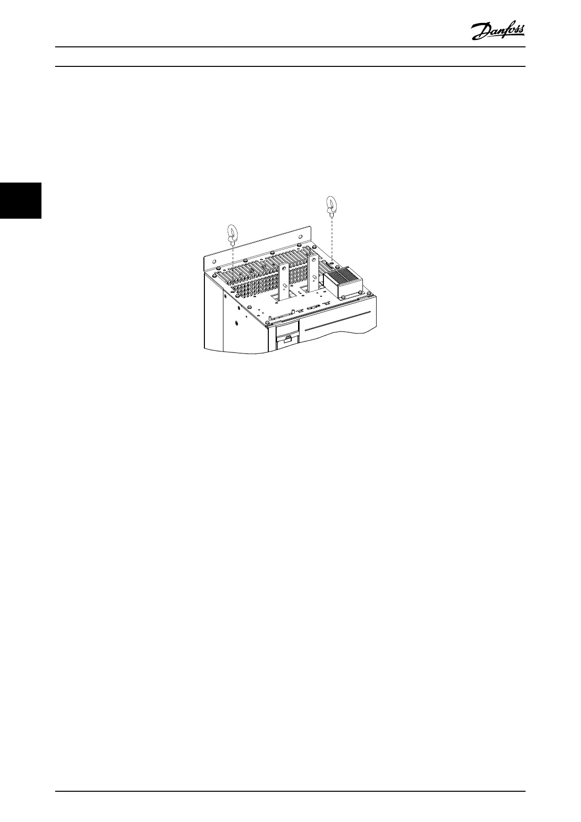
2. Install 2 eye bolts in the top of the
rst drive module. Prepare the drive module for lifting, using an appropriate
lifting harness and an overhead hoist or crane with the necessary lifting capacity. See chapter 4.1.2 Lifting the Unit.
Illustration 4.5 Installation of Eye Bolts
3. Install the 2 bottom mounting screws and gaskets onto the mounting panel.
4. Using the crane or hoist, lift the drive module and then lower the unit through the top of the cabinet frame. Align
the bottom mounting holes of the unit with the 2 bottom mounting screws on the mounting panel.
5. Verify that the drive module is correctly aligned on the mounting panel and then secure the bottom of the unit to
the panel with the 2 hex nuts. See Illustration 4.6. Torque the hex nuts. Refer to chapter 7.9 Fastener Tightening
Torques.
6. Secure the top of the unit to the mounting panel with M10x26 screws, and then torque the screws.
7. Line up the groove on the microswitch with the edges on each DC fuse and press rmly until the microswitch
clicks into place.
8. Install 2 DC fuses with microswitches onto the tops of the DC-link terminals on each drive module. The
microswitches should be installed on the outer side of each terminal. Refer to Illustration 3.1.
9. Secure each fuse with 2 M10 screws and torque the screws.
10. Install the next drive module.
Mechanical Installation
VLT
®
Parallel Drive Modules
16 Danfoss A/S © 08/2017 All rights reserved. MG37K302
44
 Loading...


