5.10.2.2 Wiring to Control Terminals
Terminal plugs can be removed for easy access.
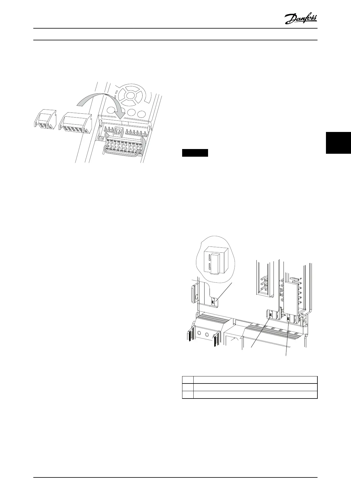
Illustration 5.10 Removal of Control Terminals
5.10.2.3 Enabling Motor Operation
(Terminal 27)
A jumper wire is required between terminal 12 (or 13) and
terminal 27 for the frequency converter to operate when
using factory default programming values.
•
Digital input terminal 27 is designed to receive
24 V DC external interlock command.
•
When no interlock device is used, wire a jumper
between control terminal 12 (recommended) or
13 to terminal 27. The jumper provides an
internal 24 V signal on terminal 27.
•
When the status line at the bottom of the LCP
reads AUTO REMOTE COAST, it indicates that the
unit is ready to operate but is missing an input
signal on terminal 27.
•
When factory installed optional equipment is
wired to terminal 27, do not remove that wiring.
5.10.2.4 Voltage/Current Input Selection
(Switches)
The analog mains terminals 53 and 54 allow the setting of
the input signal to voltage (0–10 V) or current (0/4–
20 mA). See Illustration 5.9 for the location of the control
terminals within the drive system.
Default parameter settings:
•
Terminal 53: Speed reference signal in open loop
(see parameter 16-61 Terminal 53 Switch Setting).
•
Terminal 54: Feedback signal in closed loop (see
parameter 16-63 Terminal 54 Switch Setting).
NOTICE
REMOVE POWER
Remove power to the frequency converter before
changing switch positions.
1. Remove the LCP (see Illustration 5.11).
2. Remove any optional equipment covering the
switches.
3. Set switches A53 and A54 to select the signal
type. U selects voltage, I selects current.
1 Bus termination switch
2 A54 switch
3 A53 switch
Illustration 5.11 Locations of Bus Termination Switch and
Switches A53 and A54
Electrical Installation Installation Guide
MG37K302 Danfoss A/S © 08/2017 All rights reserved. 35
5 5
 Loading...


