4.4 Installing the Control Shelf
NOTICE
To avoid RFI, do not route control wiring together with power cables or bus bars.
1. Remove the control shelf assembly from its package.
2. Remove the LCP from the control shelf.
3. Use some type of mounting bracket to install the control shelf. Danfoss does not supply the mounting brackets for
the control shelf. For EMC-correct installation, refer to Illustration 4.7.
4. Remove the MDCIC cover from the control shelf assembly.
5. Connect the 44-pin ribbon cables from the MDCIC card to the top of the drive modules, following the sequence
numbers indicated next to the connectors on the MDCIC.
6. Route the 44-pin ribbon cables inside the cabinet.
7. Connect the external brake fault wiring harness between the microswitch terminals and the brake jumper
connector on the top of the drive module.
8. Connect the relay wiring between relay 1 or 2 on the control shelf and the corresponding relay connector on the
top of the drive module.
9. Connect the microswitch to the microswitch connector provided on the top of the drive module. Refer to
Illustration 3.1 and Illustration 3.3.
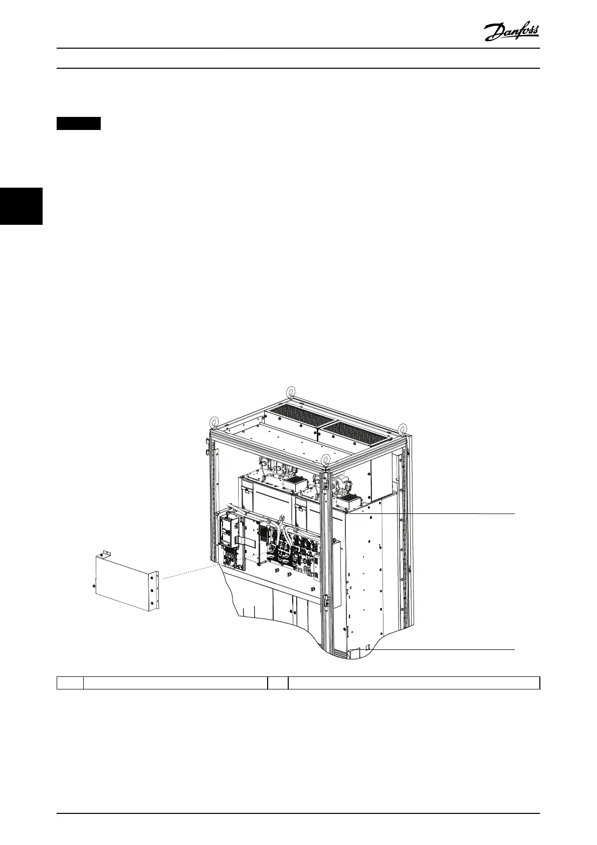
1 Control shelf must stay below this point 2 Control shelf must stay above this point
Illustration 4.7 Positioning the Control Shelf for EMC-correct Installation
Mechanical Installation
VLT
®
Parallel Drive Modules
18 Danfoss A/S © 08/2017 All rights reserved. MG37K302
44
 Loading...


