5.8 Mains Connections
There are several types of AC mains systems for supplying
power to frequency converters. Each aects the EMC
characteristics of the system. The 5-wire TN-S systems are
regarded as best regarding EMC, while the isolated IT
system is the least preferred.
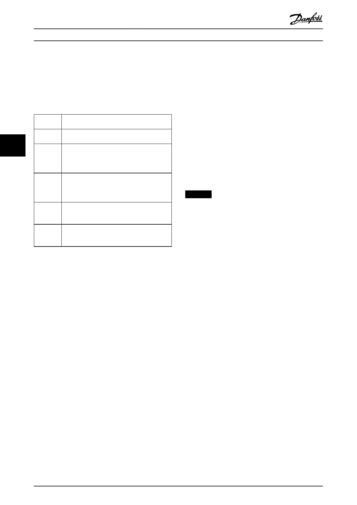
System
type
Description
TN mains
systems
There are 2 types of TN mains distribution systems:
TN-S and TN-C.
TN-S A 5-wire system with separate neutral (N) and
protective earth (PE) conductors. It provides the
best EMC properties and avoids transmitting
interference.
TN-C A 4-wire system with a common neutral and
protective earth (PE) conductor throughout the
system. The combined neutral and PE conductor
results in poor EMC characteristics.
TT mains
systems
A 4-wire system with a grounded neutral conductor
and individual grounding of the drive system. It has
good EMC characteristics when grounded properly.
IT grid
system
An isolated 4-wire system with the neutral
conductor either not grounded or grounded via an
impedance.
Table 5.11 AC Mains Systems and EMC Characteristics
5.8.1 AC Mains Terminal Connections
When making mains connections, observe the following:
•
Size the wiring based on the input current of the
frequency converter. For maximum wire sizes, see
chapter 7.1 Power-dependent Specications.
•
Comply with local and national electrical codes
for cable sizes.
5.8.1.1 Mains Terminal Connections in 2-
Drive Module Systems
Illustration 8.9 and Illustration 8.10 show the bus bar
connections for 6-pulse and 12-pulse 2-drive systems,
respectively.
•
If a common terminal design is used with a 6-
pulse, 2-drive system, there is 1 set of mains
terminals.
•
Common terminal design cannot be used with
12-pulse mains connections in a 2-drive module
systems. The mains cables are connected directly
to the drive input terminals.
•
There are individual brake terminals available in
each drive module. Connect an equal number of
recommended cables to the individual brake
terminals.
NOTICE
MULTIPLE MAINS CABLES
If connecting more than 1 set of mains terminals, use the
same number, size, and length of cables for each set of
terminals. For example, do not use 1 cable on one mains
terminal and 2 cables on another mains terminal.
1. Measure between the common terminals and the
rst common point of a phase, typically the
mains terminals.
2. For 12-pulse drive modules, the set of cables from
the 1
st
drive module connects to the star-
secondary winding of the 12-pulse transformer.
The set from the 2
nd
drive module connects to
the delta-secondary winding of the 12-pulse
transformer.
3. Strip a section of the outer cable insulation.
4. Connect the ground wire to the nearest ground
terminal.
5. Connect the 3-phase mains wiring to terminals
R/91, S/92, and T/93 using M10 screws.
6. Tighten the mains terminals. See
chapter 7.9.1 Tightening Torques for Terminals.
Electrical Installation
VLT
®
Parallel Drive Modules
28 Danfoss A/S © 08/2017 All rights reserved. MG37K302
55
 Loading...


