5.7.2.2 KTY Sensor
The frequency converter handles 3 types of KTY sensors:
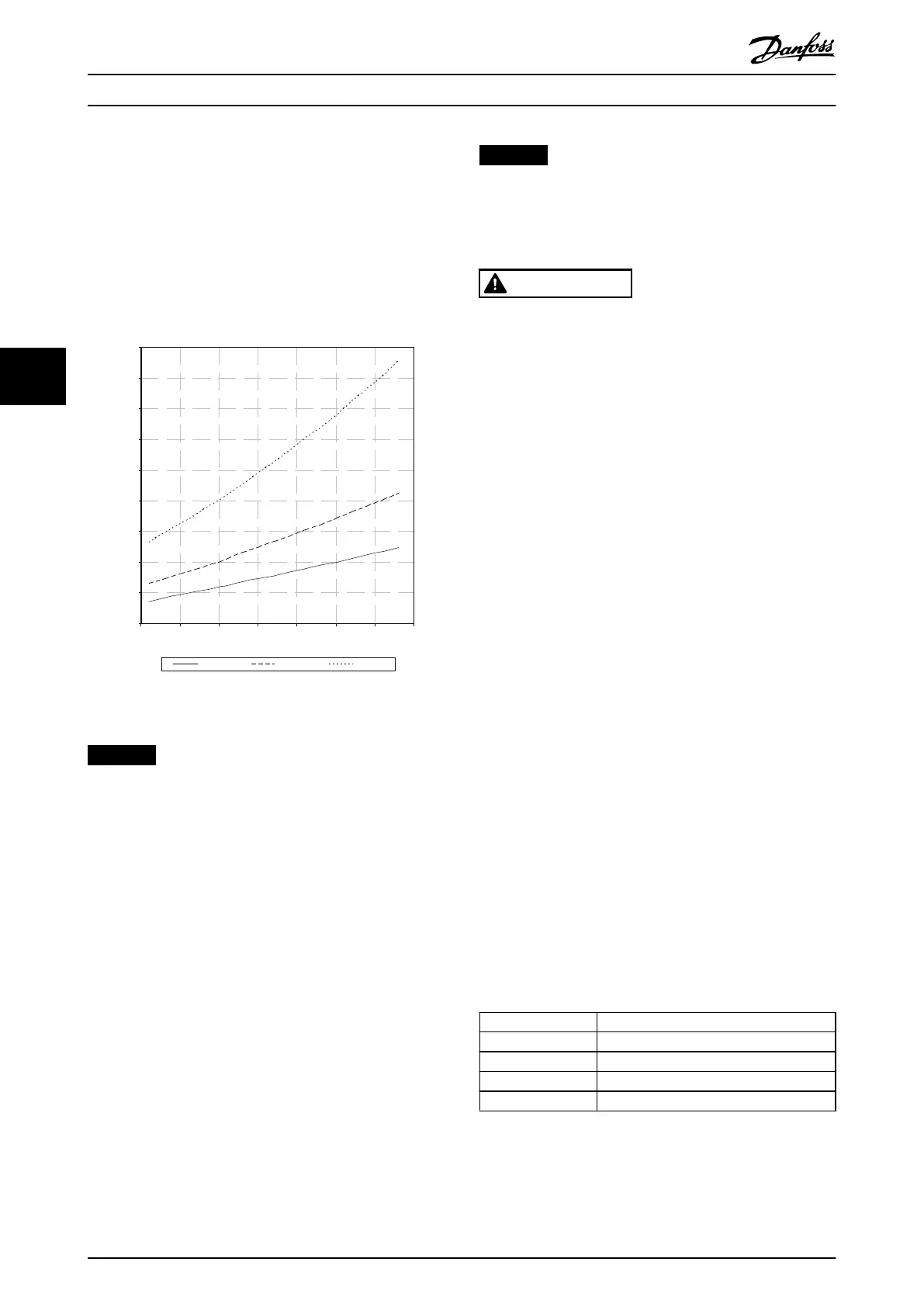
•
KTY Sensor 1: 1 kΩ at 100 °C (212 °F). Philips KTY
84-1 is an example.
•
KTY Sensor 2: 1 kΩ at 25 °C (77 °F). Philips KTY
83-1 is an example.
•
KTY Sensor 3: 1 kΩ at 25 °C (77 °F). Philips
KTY-10 is an example.
0
500
1000
1500
2000
2500
3000
3500
4000
4500
-25 0 25 50 75 100 125 150
Temperature [°C]
Resistance [Ohm]
KTY type 1 KTY type 2 KTY type 3
Illustration 5.6 KTY Type Selection
NOTICE
PELV COMPLIANCE
If short circuits occur between motor windings and the
sensor, PELV compliance is not achieved when the motor
temperature is monitored via a thermistor or KTY sensor.
Ensure that the sensor is isolated better.
5.7.2.3 Brake Resistor Thermal Switch
Installation
Each drive module has a brake fault jumper connector on
the top plate, which is used to connect the Klixon thermal
switch on the brake resistors. This connector has a pre-
installed jumper as shown in Illustration 8.3. The brake fault
jumper must always be in place to ensure proper
operation of the drive module. Without this jumper
connection, the drive module does not allow the inverter
to operate, and a brake IGBT fault is shown.
The thermal switch is a normally-closed type. If the brake
resistor temperature exceeds recommended values, the
thermal switch opens. Use 1 mm
2
(18 AWG), reinforced and
doubly insulated wire for the connection. See
Illustration 8.5.
NOTICE
Danfoss is not responsible for the failure of any Klixon
thermal switch.
5.7.3 Motor Terminal Connections
WARNING
INDUCED VOLTAGE
Induced voltage from output motor cables from dierent
frequency converters that are run together can charge
equipment capacitors even with the equipment turned
o and locked out. Failure to run output motor cables
separately or use shielded cables could result in death or
serious injury.
•
Run output motor cables separately.
Or
•
Use shielded cables.
•
Simultaneously lock out all the frequency
converters.
•
Comply with local and national electrical codes
for cable sizes. For maximum cable sizes, see
chapter 7.1 Power-dependent Specications.
•
Follow motor manufacturer wiring requirements.
•
Do not wire a starting or pole-changing device
(for example, Dahlander motor or slip ring
induction motor) between the drive system and
the motor.
5.7.3.1 Motor Cable
All types of 3-phase asynchronous standard motors can be
used with the drive system.
Connect the motor to the following terminals:
•
U/T1/96
•
V/T2/97
•
W/T3/98
•
Ground to terminal 99
Factory setting is for clockwise rotation with the drive
system output connected as follows:
Terminal number Function
96 Mains U/T1
97 V/T2
98 W/T3
99 Ground
Table 5.10 Motor Cable Terminals
Electrical Installation
VLT
®
Parallel Drive Modules
26 Danfoss A/S © 08/2017 All rights reserved. MG37K302
55
 Loading...


