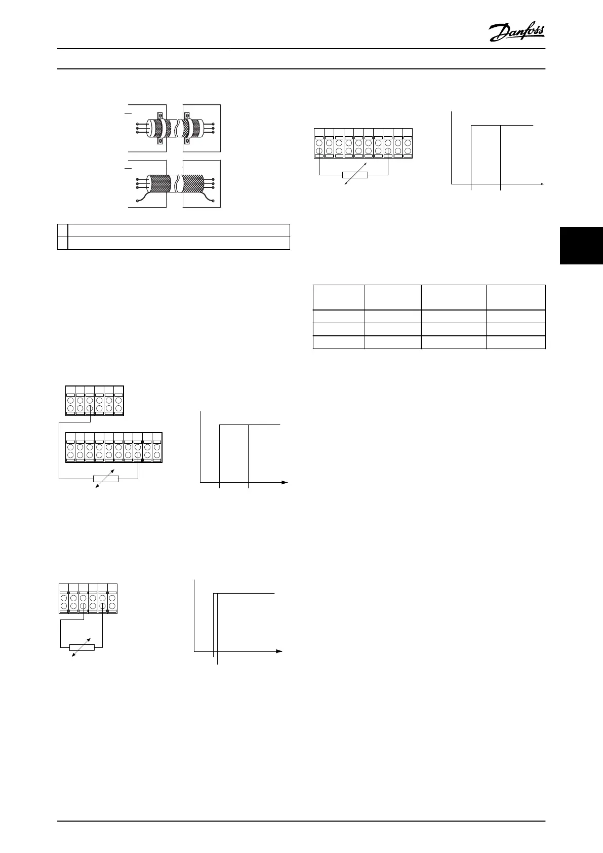
1 Correct grounding of shielded ends
2 Incorrect grounding using twisted shield ends (pigtail)
Illustration 5.2 Example of Shield Ends
5.7.2 Types of Thermal Protection
5.7.2.1 PTC Thermistor
Using a digital input and 10 V supply
PTC / Thermistor
R
OFF
ON
<800 Ω
+10V
130BA152.10
>2.7 kΩ
12 13 18 37322719 29 33 20
5550
39 42 53 54
Illustration 5.3 PTC Thermistor Connection - Digital Input with
10 V Supply
Using an analog input and 10 V supply
555039 42 53 54
R
<3.0 k Ω
>3.0 k Ω
+10V
130BA153.11
PTC / Thermistor
OFF
ON
Illustration 5.4 PTC Thermistor Connection - Analog Input with
10 V Supply
Using a digital input and 24 V as supply
PTC / Thermistor
OFF
ON
+24V
12 13 18 3732
A
2719 29 33
B
20
GND
R<6.6 k Ω >10.8 k Ω
130BA151.11
Illustration 5.5 PTC Thermistor Connection - Digital Input with
24 V Supply
Check that the selected supply voltage follows the speci-
cation of the used thermistor element.
Input digital/
analog
Supply
voltage [V]
Trip resistance
kΩ
Reset
resistance
Digital 10 >2.7
<800 Ω
Analog 10 >3.0
<3.0 kΩ
Digital 24 >10.8
<6.6 kΩ
Table 5.9 PTC Thermistor Resistance Parameters
Electrical Installation Installation Guide
MG37K302 Danfoss A/S © 08/2017 All rights reserved. 25
5 5
 Loading...


