5.10.2.5 RS485 Serial Communication
An RS485 serial communications bus can be used with the
drive system. Up to 32 nodes can be connected as a bus,
or via drop cables from a common trunk line to 1 network
segment. Repeaters can be used to divide network
segments. Each repeater functions as a node within the
segment in which it is installed. Each node connected
within a given network must have a unique node address,
across all segments.
•
Connect RS485 serial communication wiring to
terminals (+)68 and (-)69.
•
Terminate each segment at both ends, using
either the termination switch (bus term on/o,
see Illustration 5.11) on the drive module, or a
biased network termination resistor.
•
Connect a large surface of the shield to ground,
for example with a cable clamp or a conductive
cable gland.
•
Maintain the same ground potential throughout
the network by applying potential-equalizing
cables.
•
Prevent impedance mismatch by using the same
type of cable throughout the entire network.
Cable Shielded twisted pair (STP)
Impedance
120 Ω
Maximum cable length
Station-to-station [m
(ft)]
500 (1640)
Total including drop
lines [m (ft)]
1200 (3937)
Table 5.15 Cable Information
5.10.3 Safe Torque O (STO)
To run STO, extra wiring for the drive system is required.
Refer to VLT
®
Frequency Converters Safe Torque O
Operating Instructions for further information.
5.11
Relay Output
The relay terminal is on the top plate of the drive module.
See Illustration 3.1. Use an extended wiring harness to
connect the relay terminal of drive module 1 (the drive
module on the far left) to the terminal blocks on the
control shelf.
NOTICE
For reference, drive modules are numbered from left to
right.
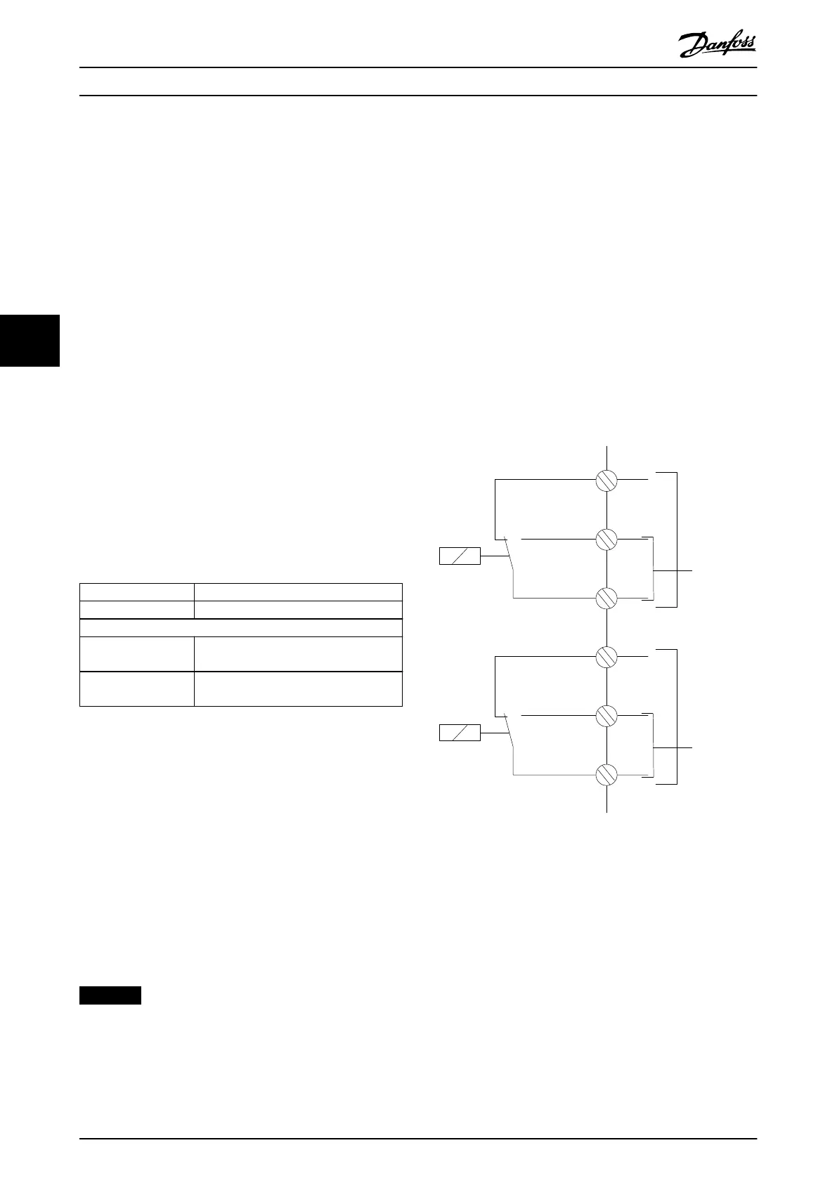
Relay 1
•
Terminal 01: Common
•
Terminal 02: Normally open 400 V AC
•
Terminal 03: Normally closed 240 V AC
Relay 2
•
Terminal 04: Common
•
Terminal 05: Normally open 400 V AC
•
Terminal 06: Normally closed 240 V AC
Relay 1 and relay 2 are programmed in
parameter 5-40 Function Relay, parameter 5-41 On Delay,
Relay, and parameter 5-42 O Delay, Relay.
Use VLT
®
Relay Card MCB 105 option module for extra
relay outputs.
130BC554.11
Relay 1
Relay 2
03
02
240 V AC, 2 A
01
06
05
04
240 V AC, 2 A
400 V AC, 2 A
400 V AC, 2 A
Illustration 5.12 Extra Relay Outputs
Electrical Installation
VLT
®
Parallel Drive Modules
36 Danfoss A/S © 08/2017 All rights reserved. MG37K302
55
 Loading...


