6 Initial Start-up
6.1 Pre-start Check List
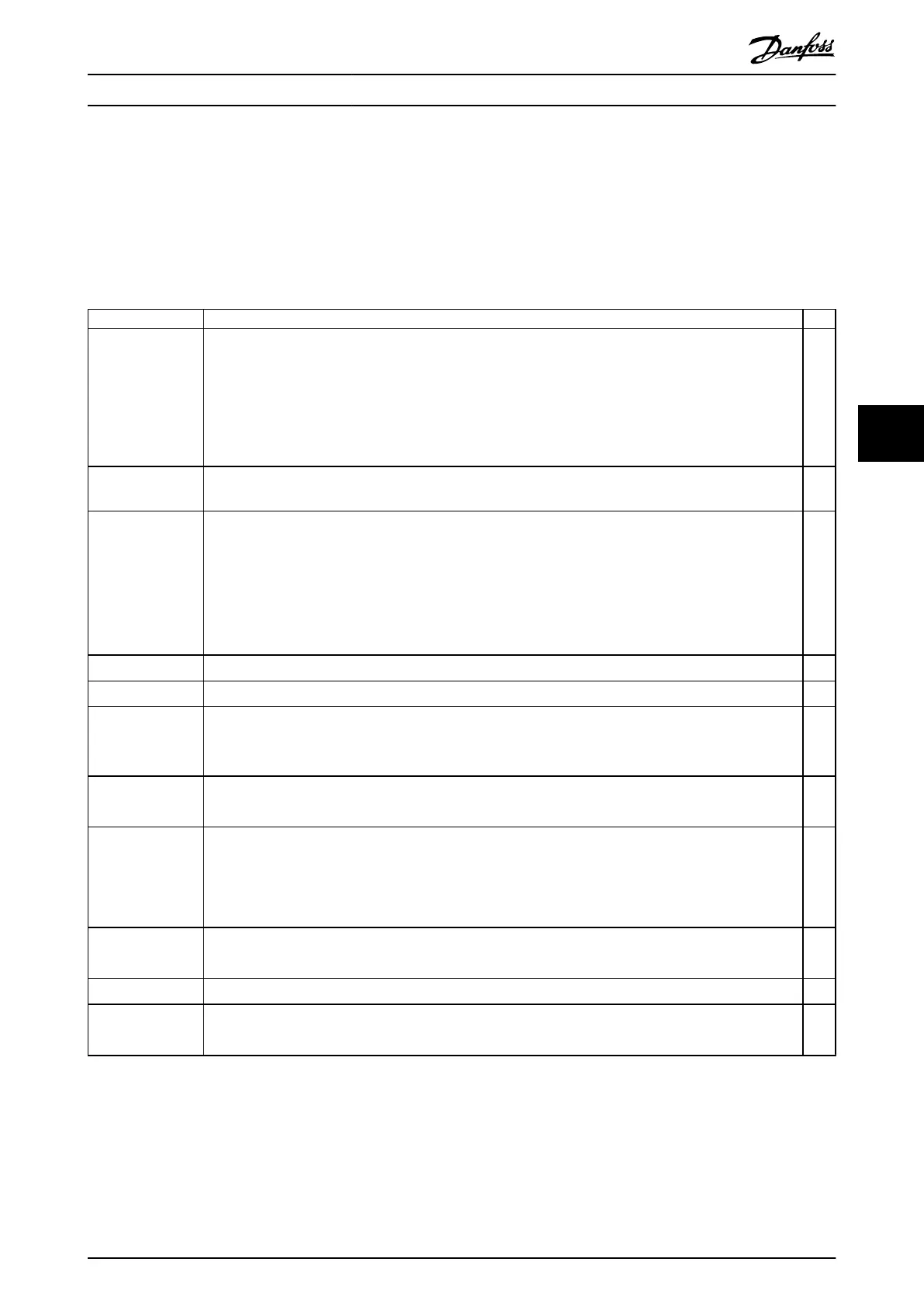
Before completing installation of the unit, inspect the entire installation as detailed in Table 6.1. Mark the check-list items
when they are completed.
Inspect for Description
☑
Auxiliary equipment
•
Look for auxiliary equipment, switches, disconnects, or input fuses/circuit breakers that reside on the input
power side of the drive system or on the output side to the motor. Ensure that they are ready for full-
speed operation.
•
Check function and installation of any sensors used for feedback to the drive system.
•
Remove any power factor correction caps on motor(s).
•
Adjust any power factor correction caps on the mains side and ensure that they are dampened.
Cable routing
•
Ensure that motor wiring and control wiring are separated or shielded, or in 3 separate metallic conduits
for high-frequency interference isolation.
Control wiring
•
Check for broken or damaged wires and loose connections.
•
Check that control wiring is isolated from power and motor wiring for noise immunity.
•
Check the voltage source of the signals, if necessary.
•
Using shielded cable or twisted pair is recommended. Ensure that the shield is terminated correctly.
•
Check that the DC-link fuse and microswitch xtures are correct. Check the microswitch cabling and the
connectors in the top of the drive module.
Cooling clearance
•
Check that there is 225 mm (9 in) of top clearance for adequate cooling.
Ambient conditions
•
Check that requirements for ambient conditions are met.
Fusing and circuit
breakers
•
Check for proper fusing or circuit breakers.
•
Check that all fuses are inserted rmly and are in operational condition, and that all circuit breakers are in
the open position.
Grounding
•
Check for good ground connections that are tight and free of oxidation.
•
Grounding to conduit, or mounting the back panel to a metal surface, is not a suitable grounding.
Input and output
power wiring
•
Check for loose connections.
•
Check that motor and mains are in separate conduit or separated shielded cables.
•
Check that the shields are properly grounded.
•
Check that the DC-link connections are properly made.
Panel interior
•
Inspect that the unit interior is free of dirt, metal chips, moisture, and corrosion.
•
Check that the unit is mounted on an unpainted, metal surface.
Switches
•
Ensure that all switch and disconnect settings are in the proper positions.
Vibration
•
Check that the unit is mounted solidly, or that shock mounts are used, as necessary.
•
Check for an unusual amount of vibration.
Table 6.1 Installation Check List
Initial Start-up Installation Guide
MG37K302 Danfoss A/S © 08/2017 All rights reserved. 41
6
6
 Loading...


