5.10.2 Control Wiring
•
Isolate the control wiring from the high-power components in the drive modules.
•
When the drive module is connected to a thermistor, ensure that the thermistor control wiring is shielded and
reinforced/double insulated. A 24 V DC supply voltage is recommended. See Illustration 5.9.
NOTICE
MINIMIZE INTERFERENCE
To minimize interference, keep control wires as short as possible and separate them from high-power cables.
The control terminals are on the control shelf, directly below the LCP. The control cable is routed at the bottom of the
cabinet.
1. Follow the designated control cable routing as shown in chapter 5.10.1 Control Cable Routing.
2. Tie down all control wires.
3. Ensure optimum electrical immunity by properly connecting the shields.
Fieldbus connection
For details, see the relevant eldbus instructions.
1. Follow the designated control cable routing as shown in chapter 5.10.1 Control Cable Routing.
2. Tie down all control wires.
3. Connect the relevant options on the control card.
5.10.2.1 Control Terminal Types
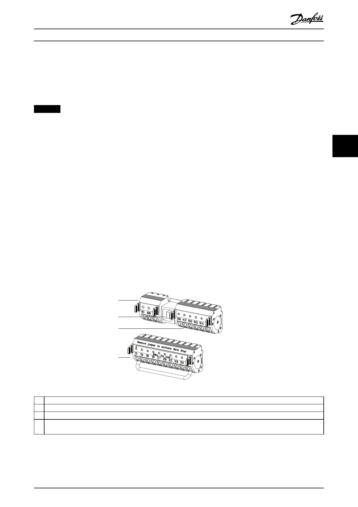
Illustration 5.9 shows the removable frequency converter connectors. Terminal functions and default settings are summarized
in Table 5.14. See Illustration 5.9 for the location of the control terminals within the unit.
1 Terminals (+)68 and (-)69 are for an RS485 serial communication connection.
2 USB port available for use with the MCT 10 Set-up Software.
3 2 analog inputs, 1 analog output, 10 V DC supply voltage, and commons for the inputs and output.
4 4 programmable digital inputs terminals, 2 extra digital terminals programmable as either input or output, a 24 V DC terminal supply
voltage, and a common for optional customer-supplied 24 V DC voltage.
Illustration 5.9 Control Terminal Locations
Electrical Installation Installation Guide
MG37K302 Danfoss A/S © 08/2017 All rights reserved. 33
5 5
 Loading...


