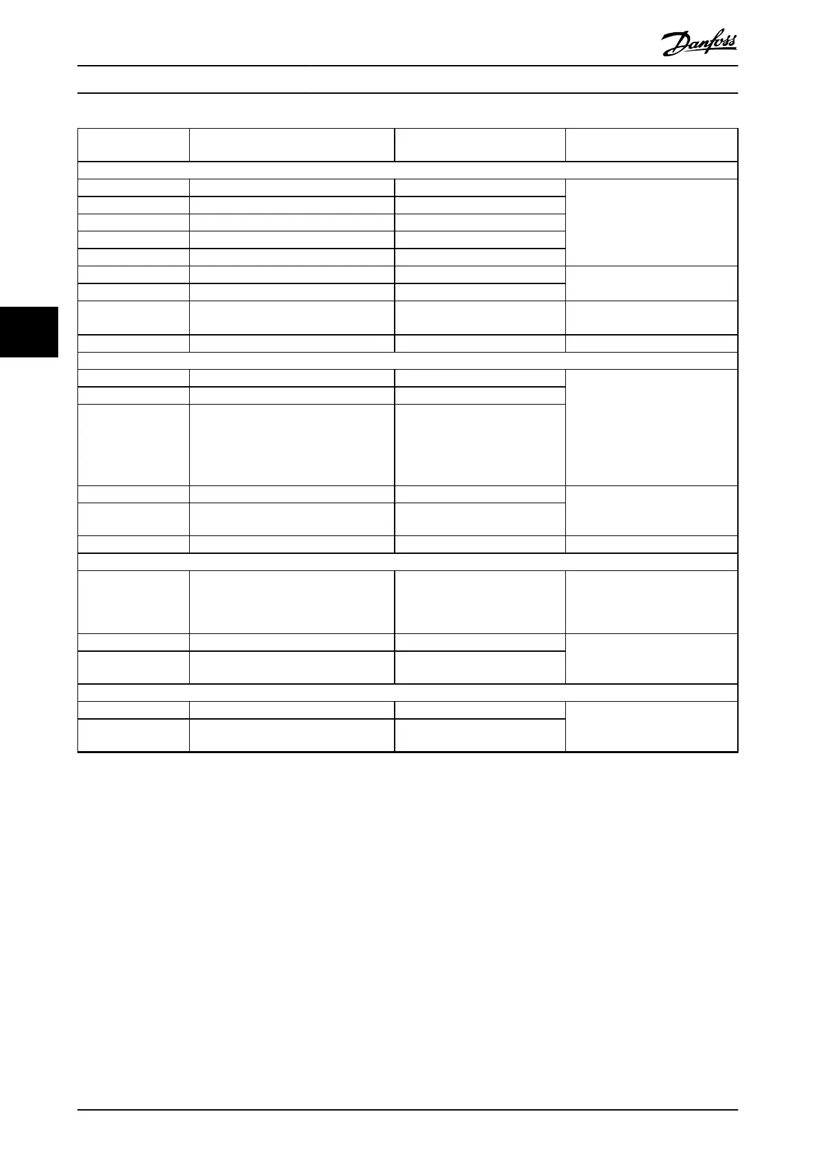
Terminal Parameter Default
setting
Description
Digital inputs/outputs
12, 13 – +24 V DC
Digital inputs. 24 V DC supply
voltage. Maximum output current
is 200 mA total for all 24 V loads.
Usable for digital inputs and
external transducers.
18 Parameter 5-10 Terminal 18 Digital Input [8] Start
19 Parameter 5-11 Terminal 19 Digital Input [10] Reversing
32 Parameter 5-14 Terminal 32 Digital Input [0] No operation
33 Parameter 5-15 Terminal 33 Digital Input [0] No operation
27 Parameter 5-12 Terminal 27 Digital Input [2] Coast inverse Selectable for digital input and
output. Default setting is input.
29 Parameter 5-13 Terminal 29 Digital Input [14] Jog
20 – – Common for digital inputs and 0 V
potential for 24 V supply.
37 – Safe Torque O (STO) Safe input (optional). Used for STO.
Analog inputs/outputs
39 – – Common for analog output
Programmable analog output. The
analog signal is 0–20 mA or 4–
20 mA at a maximum of 500 Ω
10 V DC analog supply voltage.
15 mA maximum commonly used
for potentiometer or thermistor.
42 Parameter 6-50 Terminal 42 Output Speed 0 – high limit
50 – +10 V DC
53 Parameter group 6-1* Analog Input 1 Reference Analog input. Selectable for
voltage or current. Switches A53
and A54 select mA or V.
54 Parameter group 6-2* Analog Input 2 Feedback
55 – – Common for analog input
Serial communication
61 – – Integrated RC-lter for cable shield.
ONLY for connecting the shield
when experiencing EMC problems.
68 (+) Parameter group 8-3 FC Port Settings – RS485 Interface. A control card
switch is provided for termination
resistance.
69 (-) Parameter group 8-3 FC Port Settings –
Relays
01, 02, 03 Parameter 5-40 Function Relay [0] [9] Alarm Form C relay output. Usable for AC
or DC voltage and resistive or
inductive loads.
04, 05, 06 Parameter 5-40 Function Relay [1] [5] Running
Table 5.14 Terminal Description
Extra terminals:
•
Two form C relay outputs. Location of the outputs depends on frequency converter conguration.
•
Terminals on built-in optional equipment. See the manual provided with the equipment option.
Electrical Installation
VLT
®
Parallel Drive Modules
34 Danfoss A/S © 08/2017 All rights reserved. MG37K302
55
 Loading...


