5.12.1 Using Shielded Control Cables
Danfoss recommends braided shielded/armored cables to optimize EMC immunity of the control cables and the EMC
emission from the motor cables.
The ability of a cable to reduce the incoming and outgoing radiation of electric noise depends on the transfer impedance
(Z
T
). The shield of a cable is normally designed to reduce the transfer of electric noise. However, a shield with a lower
transfer impedance (Z
T
) value is more eective than a shield with a higher transfer impedance (Z
T
).
Cable manufacturers rarely state the transfer impedance (Z
T
), but it is often possible to estimate transfer impedance (Z
T
) by
assessing the physical design of the cable, such as:
•
The conductibility of the shield material.
•
The contact resistance between the individual shield conductors.
•
The shield coverage, that is the physical area of the cable covered by the shield - often stated as a percentage
value.
•
Shield type, that is braided or twisted pattern.
175ZA166.13
0,01 0,1 1 10 100 MHz
10²
10³
10¹
1
10¹
10²
10
10³
10
a
b
c
d
e
f
g
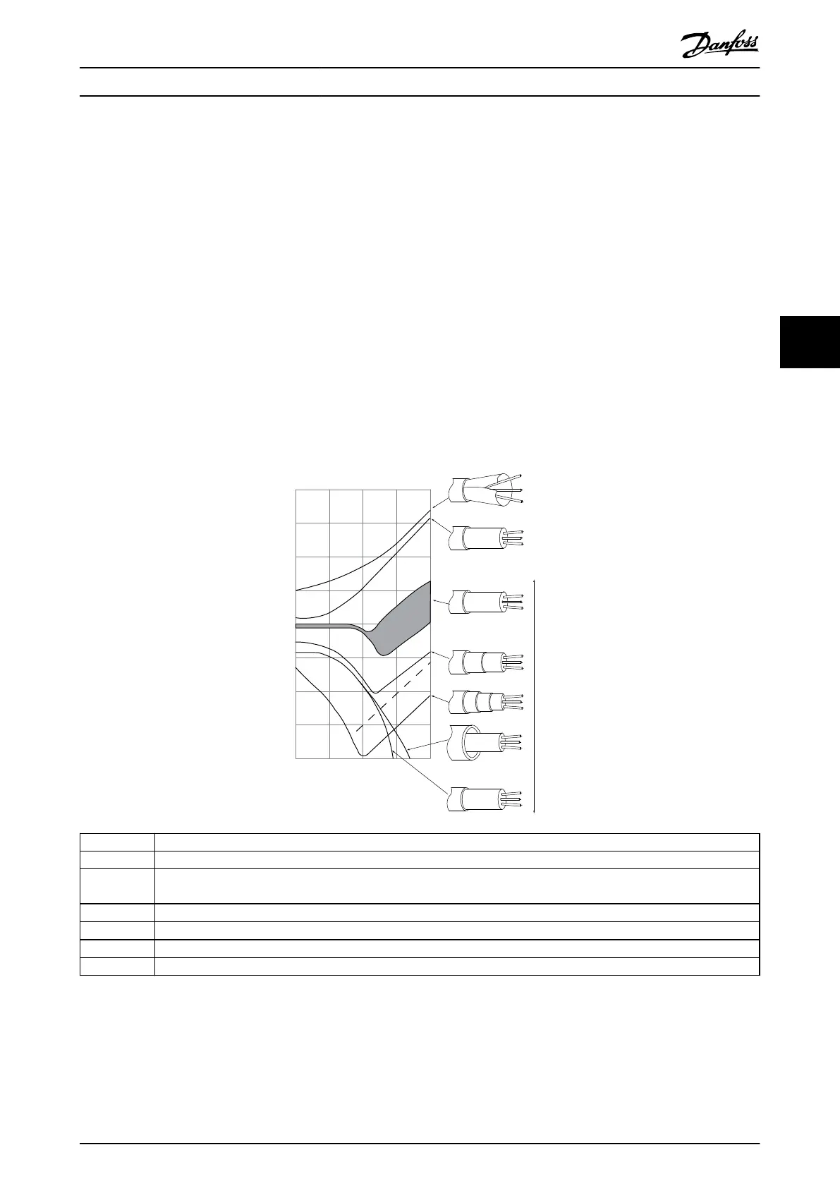
The lower the Z the better the cable shielding performance
Transfer impedance, Z
t
mΩ/m
a Aluminum-clad with copper wire.
b Twisted copper wire or armored steel wire cable.
c Single-layer braided copper wire with varying percentage shield coverage (this type of cable is the typical Danfoss
reference cable).
d Double-layer braided copper wire.
e Twin layer of braided copper wire with a magnetic, shielded/armored intermediate layer.
f Cable that runs in copper tube or steel tube.
g Lead cable with 1.1 mm (0.04 in) wall thickness.
Illustration 5.14 Cable Shielding Performance
Electrical Installation Installation Guide
MG37K302 Danfoss A/S © 08/2017 All rights reserved. 39
5 5

 Loading...


