9 Warnings and Alarms
9.1 System Monitoring
The frequency converter monitors the condition of its
input power, output, and motor factors as well as other
system performance indicators. A warning or alarm does
not necessarily indicate a problem internal to the
frequency converter itself. In many cases, it indicates failure
conditions from:
•
input voltage
•
motor load
•
motor temperature
•
external signals
•
other areas monitored by internal logic
Investigate as indicated in the alarm or warning.
9.2 Warning and Alarm Types
9.2.1 Warnings
A warning is issued when an alarm condition is impending
or when an abnormal operating condition is present and
may result in the frequency converter issuing an alarm. A
warning clears by itself when the abnormal condition is
removed.
9.2.2
Alarm Trip
An alarm is issued when the frequency converter is
tripped, that is, the frequency converter suspends
operation to prevent frequency converter or system
damage. The motor coasts to a stop. The frequency
converter logic continues to operate and monitors the
frequency converter status. After the fault condition is
remedied, reset the frequency converter. It is then ready to
start operation again.
A trip can be reset in any of 4 ways:
•
Press [Reset] on the LCP
•
Digital reset input command
•
Serial communication reset input command
•
Auto reset
9.2.3
Alarm Trip-lock
An alarm that causes the frequency converter to trip-lock
requires that input power is cycled. The motor coasts to a
stop. The frequency converter logic continues to operate
and monitors the frequency converter status. Remove
input power to the frequency converter and correct the
cause of the fault, then restore power. This action puts the
frequency converter into a trip condition as described in
chapter 9.2.2 Alarm Trip and may be reset in any of the 4
ways.
9.3 Warning and Alarm Displays
130BP085.11
Status
0.0Hz 0.000psi 0.00A
0.0Hz
1:0 - Off
!Live zero error [W2]
Off Remote Stop
!1(1)
Illustration 9.1 Warning Display
An alarm or trip-lock alarm flashes in the display along
with the alarm number.
130BP086.11
Status
0.0Hz 0.000kW 0.00A
0.0Hz
0
Earth Fault [A14]
Auto Remote Trip
1(1)
Illustration 9.2 Alarm Display
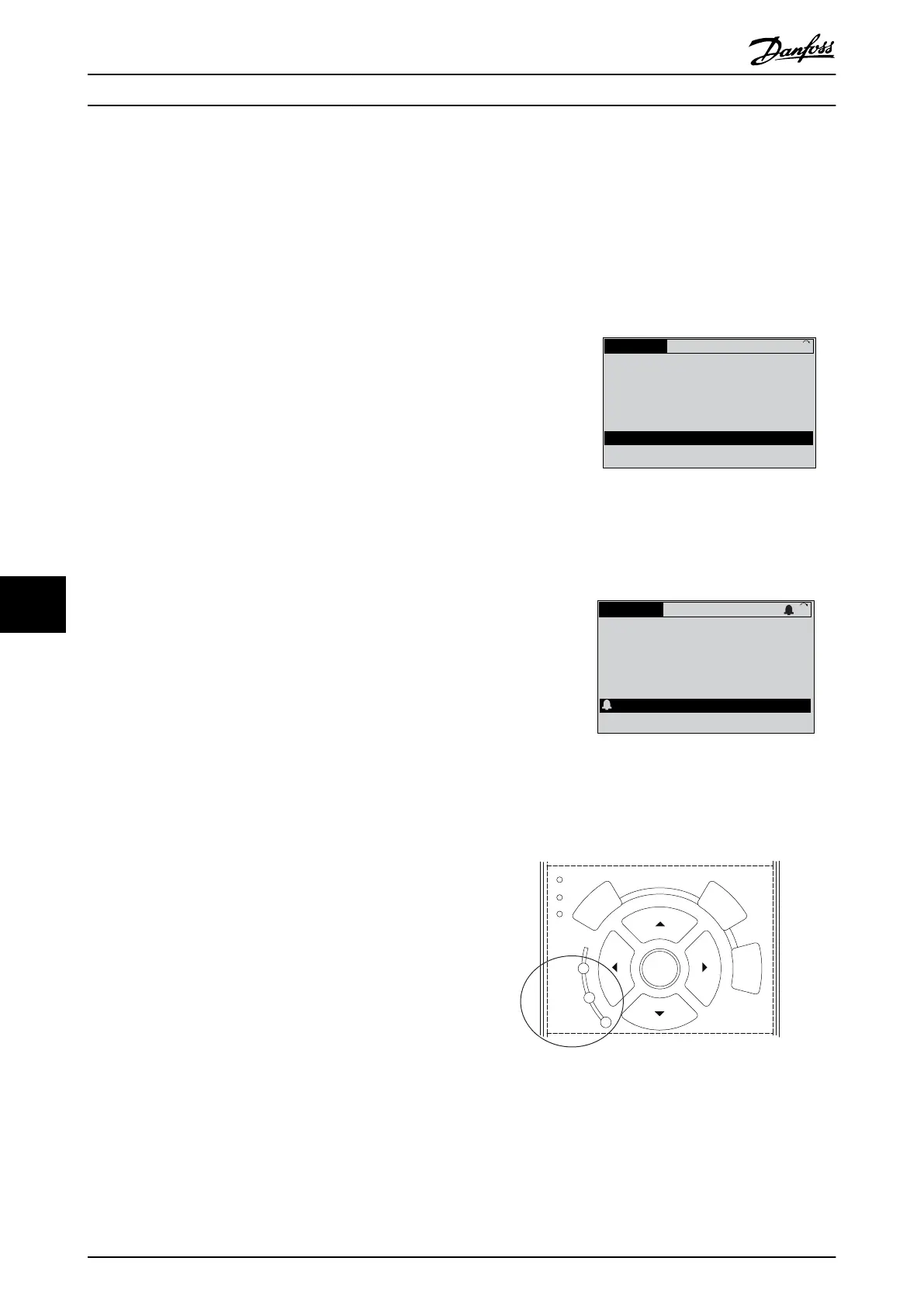
In addition to the text and alarm code in the display, there
are 3 status indicator lights.
Back
Cancel
Info
OK
On
Alarm
Warn.
130BB467.11
Illustration 9.3 Status Indicator Lights
Warnings and Alarms Operating Instructions
122 Danfoss A/S © Rev. 2014-07-29 All rights reserved. MG37A202
99

 Loading...


