5.1.9 Initialisation to Default Settings
There are 2 ways to initialise the unit to default:
Recommended initialisation and manual initialisation.
Each method has a different impact.
5.1.9.1 Recommended Initialisation Method
Initialisation via 14-22 Operation Mode)
1.
Select 14-22 Operation Mode
2. Press [OK]
3.
Select Initialisation
4. Press [OK]
5. Remove power to the unit and wait for the
display to turn off.
6. Reconnect power to reset the unit.
7. Press [Reset]
14-22 Operation Mode initialises all except:
Parameter 14-50 RFI Filter
8-31 Address
8-32 Baud Rate
8-35 Minimum Response Delay
8-36 Max Response Delay
8-37 Maximum Inter-Char Delay
15-00 Operating hours to 15-05 Over Volt's
15-20 Historic Log: Event to 15-22 Historic Log: Time
15-30 Alarm Log: Error Code to 15-32 Alarm Log: Time
NOTICE
Parameters selected in 0-25 My Personal Menu, stays
present, with default factory setting.
5.1.9.2 Manual Initialisation Method
NOTICE
When carrying out manual initialisation, serial communi-
cation, RFI filter settings, and fault log settings are reset.
Removes parameters selected in 0-25 My Personal Menu.
1. Disconnect from mains and wait until the
display turns off.
2. Press [Status] - [Main Menu] - [OK] at the same
time while power-up for graphical LCP
3. Release the keys after 5 s
4. The unit is now programmed according to
default settings
This parameter initialises all except:
15-00 Operating hours
15-03 Power Up's
15-04 Over Temp's
15-05 Over Volt's
5.1.10
RS-485 Bus Connection
A frequency converter or active filter can be connected to
a controller (or master) together with other loads using the
RS-485 standard interface. Terminal 68 is connected to the
P signal (TX+, RX+), while terminal 69 is connected to the
N signal (TX-, RX-).
To avoid potential equalising currents in the screen,
ground the cable screen via terminal 61, which is
connected to the frame via an RC-link.
Bus termination
Terminate the RS-485 bus by a resistor network at both
ends. If the frequency converter or active filter is the first
or the last device in the RS-485 loop, set the switch S801
on the control card for ON.
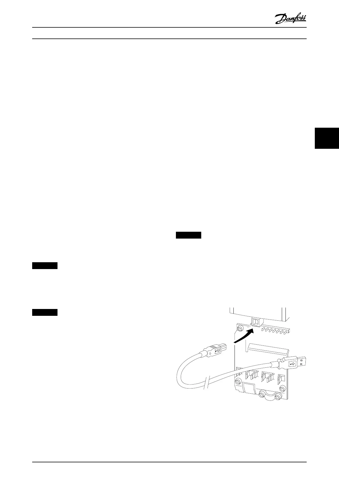
5.1.11
Connection to a PC
To program the unit from a PC, install the PC-based
configuration tool MCT 10 Set-up Software.
The PC is connected via a standard (host/device) USB cable
to the unit, or via the RS-485 interface.
NOTICE
The USB connection is galvanically isolated from the
supply voltage (PELV) and other high-voltage terminals.
The USB connection is connected to protection earth on
the unit. Use only an isolated laptop as PC connection to
the USB connector.
For control cable connections, see chapter 3.4.20 Electrical
Installation, Control Cables.
Illustration 5.16 Control Cable Connections
User Interface Operating Instructions
MG37A202 Danfoss A/S © Rev. 2014-07-29 All rights reserved. 47
5 5

 Loading...


