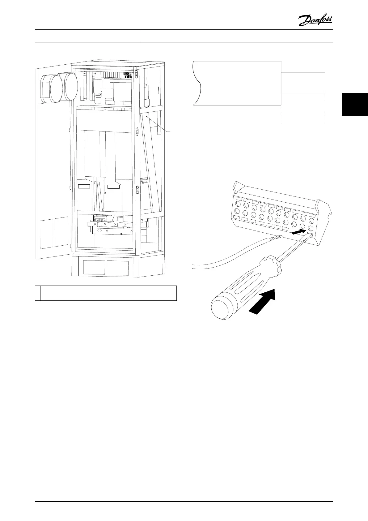
1 Routing path for the control card wiring, inside the frequency
converter enclosure.
Illustration 3.23 Control Card Wiring Path for Frame Size F18
3.4.18
Access to Control Terminals
All terminals for the control cables are located beneath the
LCP (both filter and frequency converter LCPs). They are
accessed by opening the door of the unit.
3.4.19
Electrical Installation, Control
Terminals
To connect the cable to the terminal:
1. Strip insulation by about 9–10 mm
130BA150.10
9 - 10 mm
(0.37 in)
Illustration 3.24 Length to Strip the Insulation
2. Insert a screwdriver (max. 0.4x2.5 mm) in the
square hole.
3. Insert the cable in the adjacent circular hole.
Illustration 3.25 Inserting the Cable in the Terminal Block
4. Remove the screwdriver. The cable is now
mounted in the terminal.
To remove the cable from the terminal:
1. Insert a screwdriver (max. 0.4 x 2.5 mm) in the
square hole.
2. Pull out the cable.
Installation
Operating Instructions
MG37A202 Danfoss A/S © Rev. 2014-07-29 All rights reserved. 31
3 3

 Loading...


