To run STO, additional wiring for the frequency converter
is required. Refer to VLT
®
Frequency Converters Safe Torque
Off Operating Instructions for further information.
3.4.21 Switches S201, S202, and S801
Use switches S201 (A53) and S202 (A54) to select a current
(0-20 mA) or a voltage (-10 V to 10 V) configuration of the
analog input terminals 53 and 54.
Switch S801 (BUS TER.) can be used to enable termination
on the RS-485 port (terminals 68 and 69).
See Illustration 3.28.
Default setting:
S201 (A53) = OFF (voltage input)
S202 (A54) = OFF (voltage input)
S801 (Bus termination) = OFF
NOTICE
When changing the function of S201, S202 or S801 do
not use force for the switch-over. Remove the LCP cradle
when operating the switches. The switches must not be
operated with power on the frequency converter.
Illustration 3.29 Remove the LCP Cradle to Access Switches
3.4.22
Serial Communication
RS-485 is a 2-wire bus interface compatible with multi-drop
network topology, i.e. nodes can be connected as a bus, or
via drop cables from a common trunk line. A total of 32
nodes can be connected to one network segment.
Repeaters divide networks.
NOTICE
Each repeater functions as a node within the segment in
which it is installed. Each node connected within a given
network must have a unique node address, across all
segments.
Terminate each segment at both ends, using either the
termination switch (S801) of the frequency converters or a
biased termination resistor network. Always use screened
twisted pair (STP) cable for bus cabling, and always follow
good common installation practice.
Low-impedance ground connection of the screen at every
node is important, including at high frequencies. Thus,
connect a large surface of the screen to ground, for
example with a cable clamp or a conductive cable gland. It
may be necessary to apply potential-equalizing cables to
maintain the same ground potential throughout the
network - particularly in installations with long cables.
To prevent impedance mismatch, always use the same
type of cable throughout the entire network. When
connecting a motor to the frequency converters, always
use screened motor cable.
Cable Screened twisted pair (STP)
Impedance
120 Ω
Cable length
[m]
Max. 1200 (including drop lines)
Max. 500 station-to-station
Table 3.13 Cable Recommendations
3.5
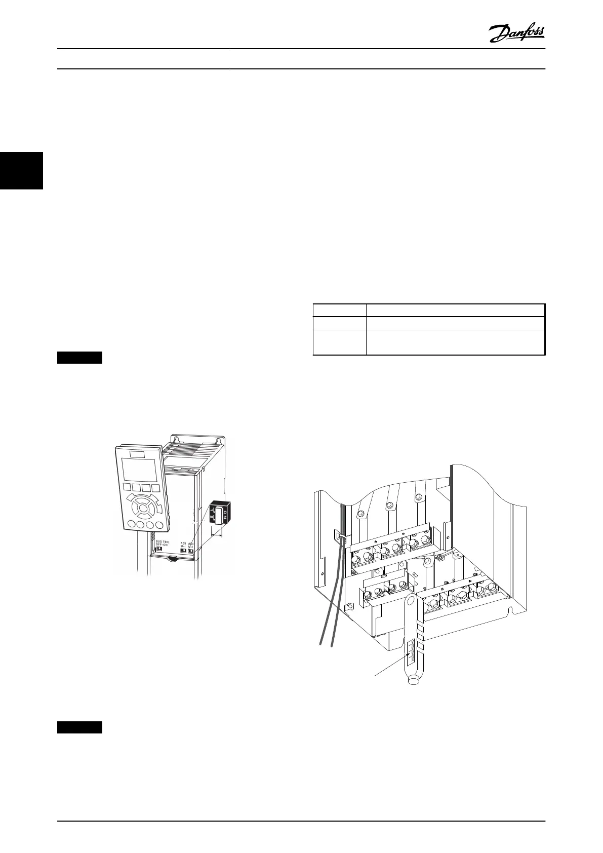
Final Set-up and Test
Correct torque is imperative for all electrical connections.
Incorrect torque results in a bad electrical connection. Use
a torque wrench to ensure correct torque.
176FA247.12
Nm/in-lbs
-DC 88
+DC 89
R/L1 91
S/L2 92
T/L3 93
U/T1 96
V/T2 97
W/T3
Illustration 3.30 Use a Torque Wrench to Tighten the Bolts
Installation Operating Instructions
34 Danfoss A/S © Rev. 2014-07-29 All rights reserved. MG37A202
33

 Loading...


