7.3 Connection Examples for Control of
Motor with External Signal Provider
NOTICE
The following examples refer only to the frequency
converter control card (right LCP), not the filter.
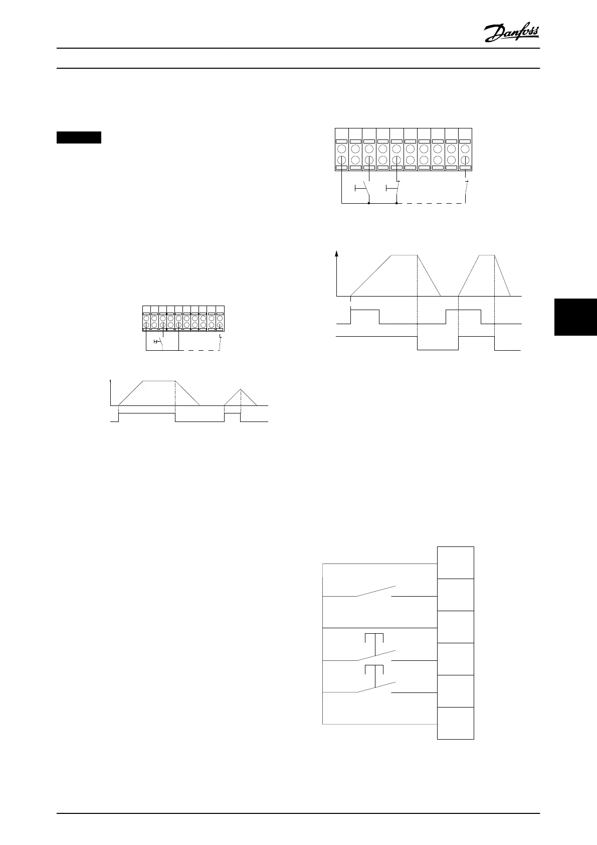
7.3.1 Start/Stop
Terminal 18 = 5-10 Terminal 18 Digital Input [8] Start
Terminal 27 = 5-12 Terminal 27 Digital Input [0] No
operation (Default coast inverse)
Terminal 37 = Safe stop
12 13 18 37
130BA155.12
322719 29 33 20
P 5-12 [0]
P 5-10 [8]
Start/Stop
+24V
Speed
Safe Stop
Start/Stop
[18]
Illustration 7.5 Start/Stop Parameters
7.3.2
Pulse Start/Stop
Terminal 18 = 5-10 Terminal 18 Digital Input [9] Latched
start
Terminal 27= 5-12 Terminal 27 Digital Input [6] Stop inverse
Terminal 37 = Safe torque off
12 13 18 37
130BA156.12
322719 29 33 20
P 5 - 12 [6]
P 5 - 10[9]
+24V
Speed
Start Stop inverse Safe Stop
Start (18)
Start (27)
Illustration 7.6 Pulse Start/Stop Parameters
7.3.3
Speed Up/Down
Terminals 29/32 = Speed up/down
Terminal 18 = 5-10 Terminal 18 Digital Input [9]
Start (default)
Terminal 27 = 5-12 Terminal 27 Digital Input [19]
Freeze reference
Terminal 29 = 5-13 Terminal 29 Digital Input [21]
Speed up
Terminal 32 = 5-14 Terminal 32 Digital Input [22]
Speed down
12
18
27
29
32
37
+24V
Par. 5-10
Par. 5-12
Par. 5-13
Par. 5-14
130BA021.12
Illustration 7.7 Speed Control Parameters
Application Examples Operating Instructions
MG37A202 Danfoss A/S © Rev. 2014-07-29 All rights reserved. 117
7 7

 Loading...


