Parameters
FC
+24 V
+24 V
D IN
D IN
D IN
COM
D IN
D IN
D IN
D IN
+10 V
A IN
A IN
COM
A OUT
COM
R1R2
12
13
18
19
20
27
29
32
33
37
50
53
54
55
42
39
01
02
03
04
05
06
130BB839.10
Function Setting
4-30 Motor
Feedback Loss
Function
[1] Warning
4-31 Motor
Feedback Speed
Error
100 RPM
4-32 Motor
Feedback Loss
Timeout
5 s
7-00 Speed PID
Feedback Source
[2] MCB 102
17-11 Resolution
(PPR)
1024*
13-00 SL
Controller Mode
[1] On
13-01 Start Event
[19] Warning
13-02 Stop Event
[44] Reset
key
13-10 Comparato
r Operand
[21] Warning
no.
13-11 Comparato
r Operator
[1] ≈*
13-12 Comparato
r Value
90
13-51 SL
Controller Event
[22]
Comparator 0
13-52 SL
Controller Action
[32] Set
digital out A
low
Parameter 5-40 F
unction Relay
[80] SL digital
output A
*=Default Value
Notes/comments:
If the limit in the feedback
monitor is exceeded, Warning
90 is issued. The SLC monitors
Warning 90 and in the case
that Warning 90 becomes TRUE
then relay 1 is triggered.
External equipment may
indicate that service is required.
If the feedback error goes
below the limit again within 5
s, the frequency converter
continues and the warning
disappears. But relay 1 is still
triggered until [Reset] on the
LCP.
Table 7.13 Using SLC to Set a Relay
Parameters
FC
+24 V
+24 V
D IN
D IN
D IN
COM
D IN
D IN
D IN
D IN
+10 V
A IN
A IN
COM
A OUT
COM
R1R2
12
13
18
19
20
27
29
32
33
37
50
53
54
55
42
39
01
02
03
04
05
06
130BB841.10
Function Setting
1-00 Configu-
ration Mode
[0] Speed
open loop
1-01 Motor
Control Principle
[1] VVC
+
Parameter 5-40 F
unction Relay
[32] Mech.
brake ctrl.
5-10 Terminal 18
Digital Input
[8] Start*
5-11 Terminal 19
Digital Input
[11] Start
reversing
1-71 Start Delay
0.2
1-72 Start
Function
[5] VVC
+
/
FLUX
Clockwise
1-76 Start
Current
I
m,n
Parameter 2-20 R
elease Brake
Current
App.
dependent
Parameter 2-21 A
ctivate Brake
Speed [RPM]
Half of
nominal slip
of the motor
*=Default Value
Notes/comments:
Table 7.14 Mechanical Brake Control (Open Loop)
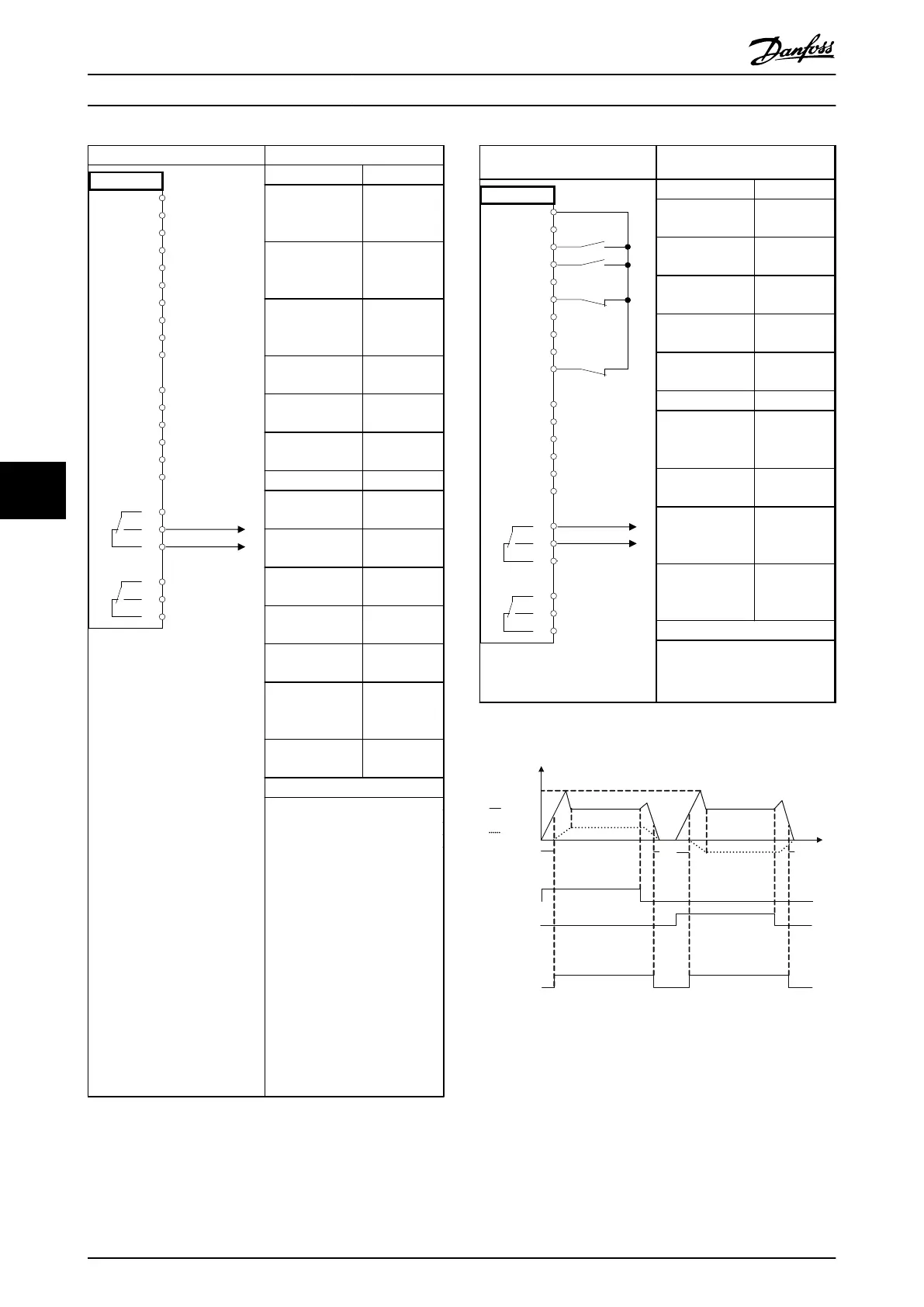
Start (18)
Start
reversing (19)
Relay output
Speed
Time
Current
1-71
1-71
2-21
2-21
1-76
Open
Closed
130BB842.10
Illustration 7.4 Mechanical Brake Control (Open Loop)
Application Examples Operating Instructions
116 Danfoss A/S © Rev. 2014-07-29 All rights reserved. MG37A202
77

 Loading...


