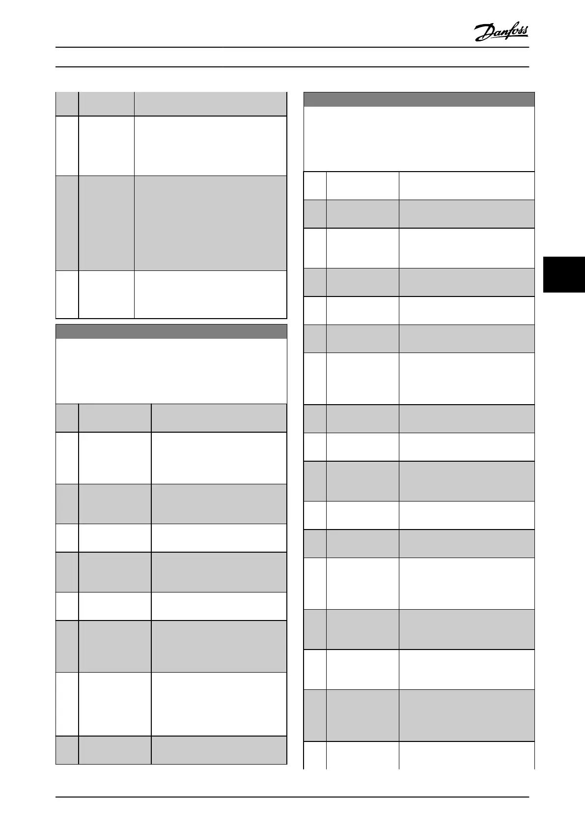
163 ATEX ETR cur.lim.warning is active, the
output is 1.
[154] ATEX ETR freq.
warning
Selectable if parameter 1-90 Motor Thermal
Protection is set to [20] Above feedback
high or [21] Thermal warning. If the
warning 165 ATEX ETR freq.lim.warning is
active, the output is 1.
[188] AHF Capacitor
Connect
The capacitors are turned on at 20%
(hysteresis of 50% gives an interval of
10%–30%). The capacitors are discon-
nected below 10%. The off delay is 10 s
and restart if the nominal power goes
above 10% during the delay. 5-80 AHF Cap
Reconnect Delay is used to guarantee a
minimum off-time for the capacitors.
[189] External fan
control
The internal logic for the internal fan
control is transferred to this output to
make it possible to control an external fan
(relevant for HP duct cooling).
5-40 Function Relay
Array [9]
(Relay 1 [0], Relay 2 [1], Relay 3 [2] (MCB 113), Relay 4 [3] (MCB
113), Relay 5 [4] (MCB 113), Relay 6 [5] (MCB 113), Relay 7 [6]
(MCB 105), Relay 8 [7] (MCB 105), Relay 9 [8] (MCB 105))
Option: Function:
[0] * No operation All digital and relay outputs are
default set to “No Operation.”
[1] Control ready The control card is ready. Control is
supplied by an external 24 V (MCB
107) and the main power to the
frequency converter is not detected.
[2] Drive ready Frequency converter is ready to
operate. Mains and control supplies
are OK.
[3] Drive rdy/rem ctrl The frequency converter is ready for
operation and is in Auto On mode
[4] Enable / no
warning
Ready for operation. No start or stop
commands have been applied (start/
disable). No warnings are active.
[5] VLT running Motor is running, and shaft torque
present.
[6] Running / no
warning
Output speed is higher than the
speed set in 1-81 Min Speed for
Function at Stop [RPM]. The motor is
running and no warnings are active.
[7] Run in range/no
warn
Motor is running within the
programmed current and speed
ranges set in 4-50 Warning Current
Low and 4-53 Warning Speed High. No
warnings are active.
[8] Run on ref/no warn Motor runs at reference speed. No
warnings are active.
5-40 Function Relay
Array [9]
(Relay 1 [0], Relay 2 [1], Relay 3 [2] (MCB 113), Relay 4 [3] (MCB
113), Relay 5 [4] (MCB 113), Relay 6 [5] (MCB 113), Relay 7 [6]
(MCB 105), Relay 8 [7] (MCB 105), Relay 9 [8] (MCB 105))
Option: Function:
[9] Alarm An alarm activates the output. No
warnings are active.
[10] Alarm or warning An alarm or a warning activates the
output.
[11] At torque limit
The torque limit set in 4-16 Torque
Limit Motor Mode or 4-17 Torque Limit
Generator Mode has been exceeded.
[12] Out of current
range
The motor current is outside the
range set in 4-18 Current Limit.
[13] Below current, low Motor current is lower than that set
in 4-50 Warning Current Low.
[14] Above current,
high
Motor current is higher than that set
in 4-51 Warning Current High.
[15] Out of speed range Output speed/frequency is outside
the frequency range set in
4-52 Warning Speed Low and
4-53 Warning Speed High.
[16] Below speed, low Output speed is lower than the
setting in 4-52 Warning Speed Low
[17] Above speed, high Output speed is higher than the
setting in 4-53 Warning Speed High.
[18] Out of feedb.
range
Feedback is outside the range set in
4-56 Warning Feedback Low and
4-57 Warning Feedback High.
[19] Below feedback,
low
Feedback is below the limit set in
4-56 Warning Feedback Low.
[20] Above feedback,
high
Feedback is above the limit set in
4-57 Warning Feedback High.
[21] Thermal warning Thermal warning turns on when the
temperature exceeds the limit either
in motor, frequency converter, brake
resistor, or connected thermistor.
[22] Ready,no thermal
W
The frequency converter is ready for
operation and there is no overtem-
perature warning.
[23] Remote,ready,no
TW
The frequency converter is ready for
operation and is in Auto On mode.
There is no overtemperature warning.
[24] Ready, Voltage OK The frequency converter is ready for
operation and the mains voltage is
within the specified voltage range
(see chapter 11 Specifications).
[25] Reverse Logic ‘1’ when CW rotation of the
motor. Logic ‘0’ when CCW rotation
Programming Operating Instructions
MG37A202 Danfoss A/S © Rev. 2014-07-29 All rights reserved. 67
6 6

 Loading...


