Make the screen connections with the largest possible
surface area (cable clamp). Use the installation devices
within the frequency converter.
Cable-length and cross-section
The frequency converter has been EMC tested with a given
length of cable. Keep the motor cable as short as possible
to reduce the noise level and leakage currents.
Switching frequency
When frequency converters are used together with sine-
wave filters to reduce the acoustic noise from a motor, the
switching frequency must be set according to
14-01 Switching Frequency.
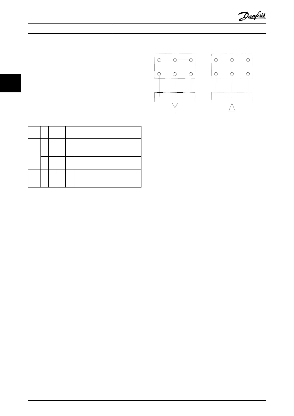
Term.
no.
96 97 98 99
U V W
PE
1)
Motor voltage 0–100% of mains
voltage.
3 wires out of motor
U1 V1 W1
PE
1)
Delta-connected
W2 U2 V2 6 wires out of motor
U1 V1 W1
PE
1)
Star-connected U2, V2, W2
U2, V2, and W2 to be interconnected
separately.
Table 3.3 Terminal Connections
1) Protective Earth Connection
U
1
V
1
W
1
175ZA114.11
96 97 98
96 97 98
FC
FC
Motor
Motor
U
2
V
2
W
2
U
1
V
1
W
1
U
2
V
2
W
2
Illustration 3.16 Y and Delta Terminal Configurations
Consider the following basic issues for electromagnetic
compatibility (EMC) during installation:
•
Safety grounding: The frequency converter has a
high leakage current and must be grounded
appropriately for safety reasons. Apply local
safety regulations.
•
High-frequency grounding: Keep the ground wire
connections as short as possible.
Connect the different ground systems at the lowest
possible conductor impedance. Keep the conductor as
short as possible and use the greatest possible surface area
for the lowest possible conductor impedance.
The metal cabinets of the different devices are mounted
on the cabinet rear plate using the lowest possible HF
impedance. Doing so avoids different HF voltages for
individual devices and the risk of radio interference
currents running in connection cables between the
devices. The radio interference is reduced.
To obtain a low HF impedance, use the fastening bolts of
the devices as HF connection to the rear plate. Remove
insulating paint or similar from the fastening points.
Installation Operating Instructions
24 Danfoss A/S © Rev. 2014-07-29 All rights reserved. MG37A202
33

 Loading...


