130BX168.10
20
19
18
17
16
15
14
13
12
11
23
22
21
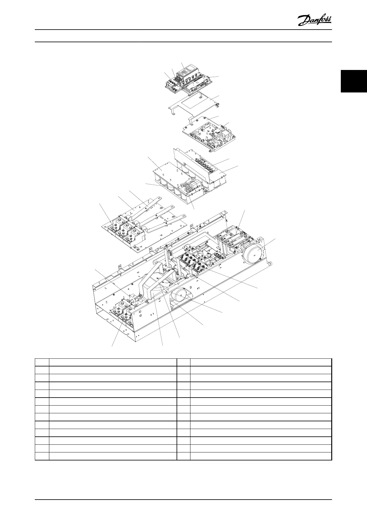
1 Control card 14 SCR and diode
2 Control input terminals 15 Fan inductor (not on all units)
3 Local control panel (LCP) 16 Soft charge resistor assembly
4 Control card C option 17 IGBT output bus bar
5 Mounting bracket 18 Fan assembly
6 Power card mounting plate 19 Output motor terminals
7 Power card 20 Current sensor
8 IGBT gate drive card 21 Mains AC power input terminals
9 Upper capacitor bank assembly 22 Input terminal mounting plate
10 Soft charge fuses 23 AC input bus bar
11 DC inductor 24 Soft charge card
12 Fan transformer 25 Lower capacitor bank assembly
13 IGBT module
Illustration 2.3 Frame Size E9 Drive Enclosure
Introduction
Operating Instructions
MG37A202 Danfoss A/S © Rev. 2014-07-29 All rights reserved. 7
2 2

 Loading...


