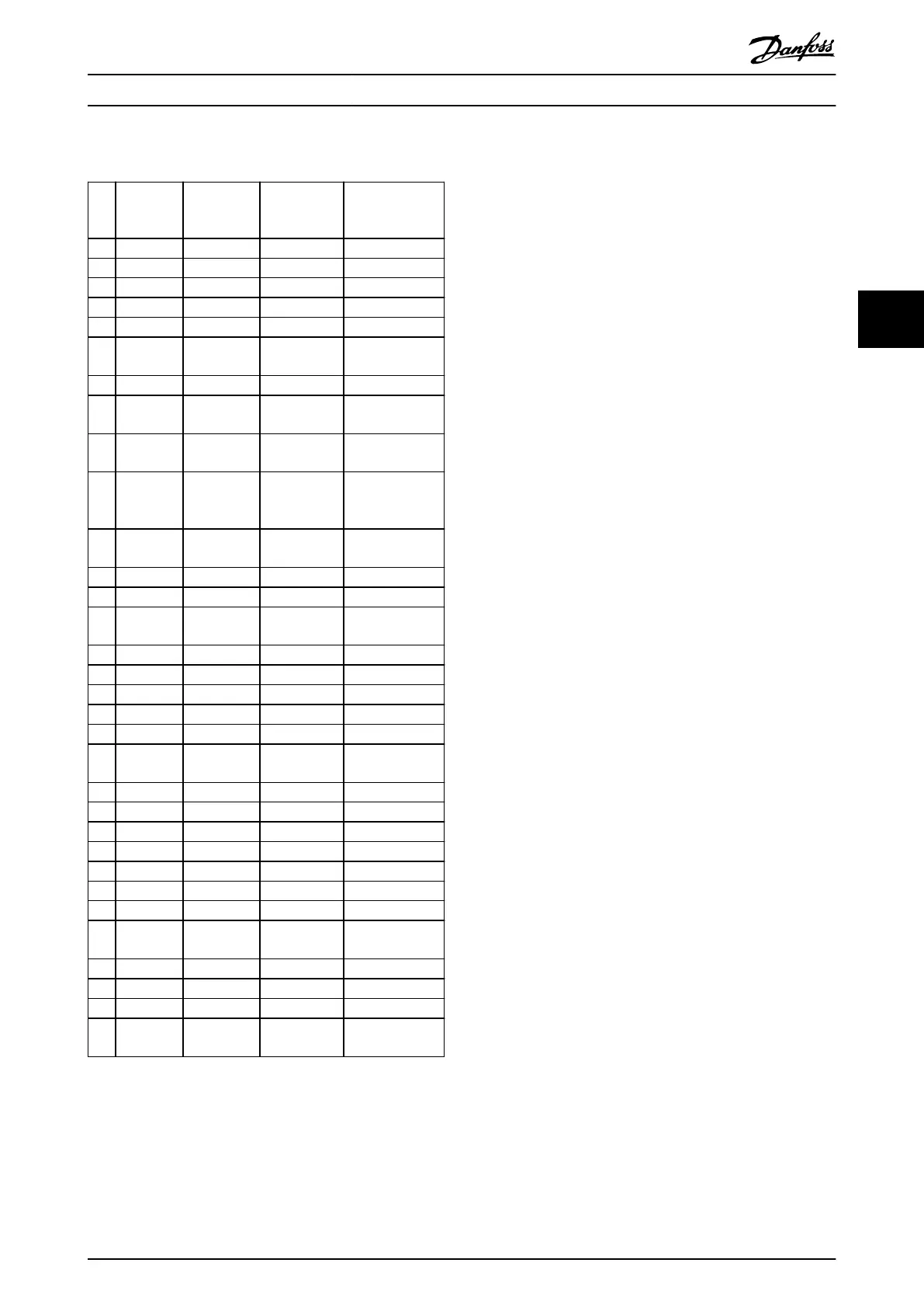
4.4 Extended Status Words
Bit Hex Dec
Parameter 16
-94 Ext.
Status Word
Parameter 16-95
Ext. Status Word
2
0 1 1 Ramping O
1 2 2 AMA running Hand/Auto
2 4 4 Start CW/CCW 0
3 8 8 0 0
4 10 16 0 0
5 20 32
Feedback
high
0
6 40 64 Feedback low 0
7 80 128
Output
current high
Control Ready
8 100 256
Output
current low
Drive Ready
9 200 512
Output
frequency
high
Quick Stop
10 400 1024
Output
frequency low
DC Brake
11 800 2048 0 Stop
12 1000 4096 0 0
13 2000 8192 Braking
Freeze Output
Request
14 4000 16384 0 Freeze Output
15 8000 32768 OVC active Jog Request
16 10000 65536 AC brake Jog
17 20000 131072 0 Start request
18 40000 262144 0 Start
19 80000 524288
Reference
high
0
20 100000 1048576 Reference low Start Delay
21 200000 2097152 0 Sleep
22 400000 4194304 0 Sleep boost
23 800000 8388608 0 Running
24 1000000 16777216 0 Bypass
25 2000000 33554432 0 Fire Mode
26 4000000 67108864 0 External Interlock
27 8000000 134217728 0
Firemodelimi-
texceed
28 10000000 268435456 0 FlyStart Active
29 20000000 536870912 0 0
30 40000000 1073741824 0 0
31 80000000 2147483648
Database
busy
0
Table 4.5 Extended Status Words
4.5
List of Warnings and Alarms
WARNING/ALARM 2, Live zero error
This warning or alarm only appears if parameter 6-01 Live
Zero Timeout Function is congured. The signal on 1 of the
analog inputs is less than 50% of the minimum value
programmed for that input. This condition can be caused
by broken wiring or a faulty device sending the signal.
Troubleshooting
•
Check connections on all the analog input
terminals. Control card terminals 53 and 54 for
signals, terminal 55 common.
•
Check that the frequency converter programming
matches the analog signal type.
WARNING/ALARM 3, No motor
No motor is connected to the output of the frequency
converter. Check the cable connection between the
frequency converter and the motor.
WARNING/ALARM 4, Mains phase loss
A phase is missing on the supply side, or the mains
voltage imbalance is too high. This message also appears
for a fault in the input rectier on the frequency converter.
Options are programmed at parameter 14-12 Function at
Mains Imbalance.
Troubleshooting
•
Check the supply voltage and supply currents to
the frequency converter.
WARNING/ALARM 7, DC overvoltage
If the DC-link voltage exceeds the limit, the frequency
converter trips after a time.
Troubleshooting
•
Extend the ramp time.
•
Activate functions in parameter 2-10 Brake
Function.
•
Activate overvoltage control in
parameter 2-17 Over-voltage Control.
WARNING/ALARM 8, DC under voltage
If the DC-link voltage (DC) drops below the undervoltage
limit, the frequency converter trips after a xed time delay.
The time delay varies with unit size.
Troubleshooting
•
Check that the supply voltage matches the
frequency converter voltage.
•
Perform an input voltage test.
WARNING/ALARM 9, Inverter overloaded
The frequency converter is about to cut out because of an
overload (too high current for too long). The counter for
electronic, thermal inverter protection issues a warning at
90% and trips at 100%, while issuing an alarm. The
frequency converter cannot be reset until the counter is
below 90%.
The fault is that the frequency converter is overloaded by
more than 100% for too long.
Troubleshooting Programming Guide
MG18B502 Danfoss A/S © 04/2018 All rights reserved. 101
4 4
 Loading...


