3.6 Main Menu - Digital In/Out - Group 5
3.6.1 5-0* Digital I/O Mode
Parameters for conguring the input and output using
NPN and PNP.
NOTICE
These parameters cannot be adjusted while the motor is
running.
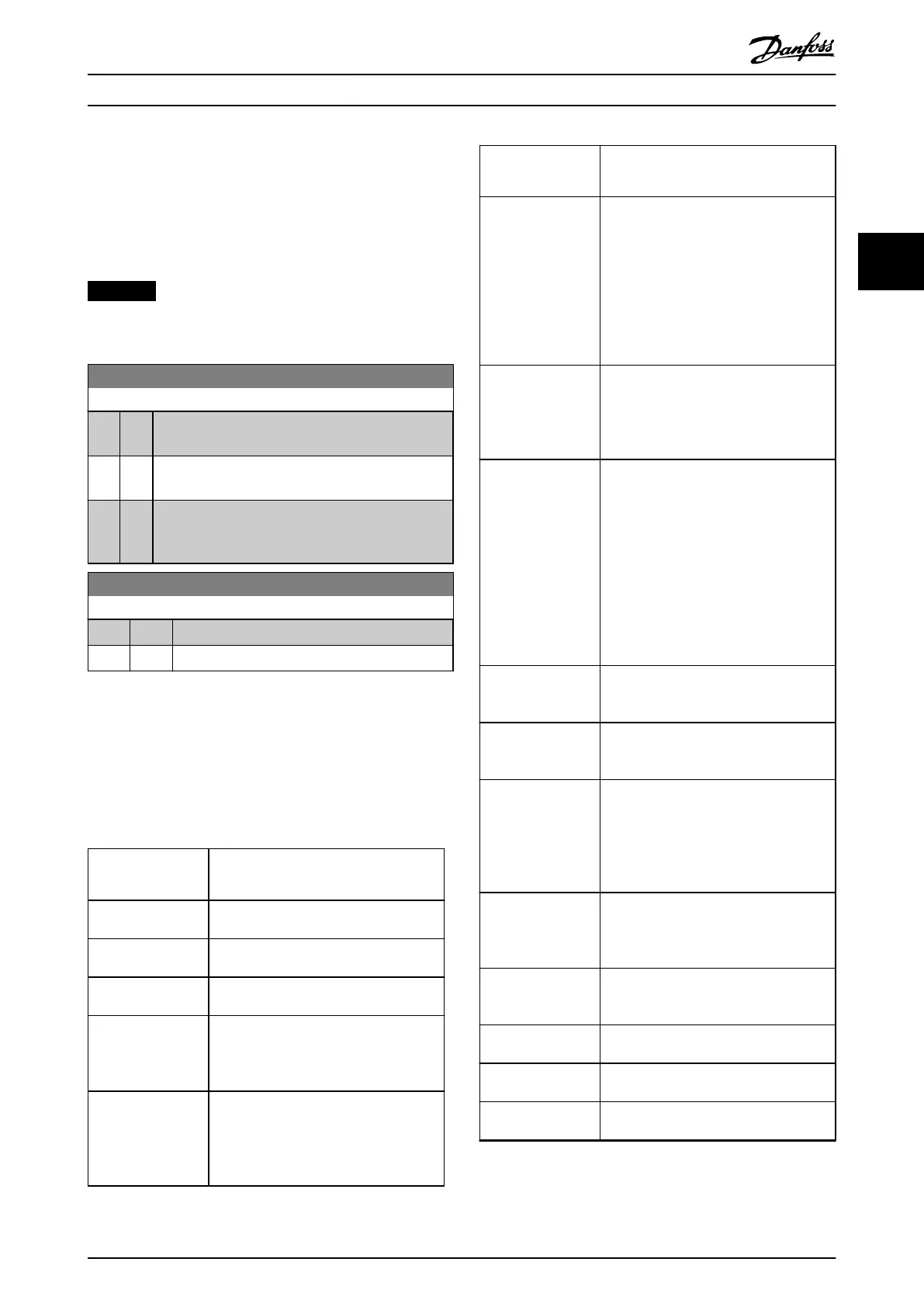
5-00 Digital Input Mode
Option: Function:
Set NPN or PNP mode for digital inputs 18, 19, and
27. Digital input mode.
[0] * PNP Action on positive directional pulses (0). PNP systems
are pulled down to ground (GND).
[1] NPN Action on negative directional pulses (1). NPN
systems are pulled up to +24 V, internally in the
frequency converter.
5-03 Digital Input 29 Mode
Option: Function:
[0] * PNP Set to PNP mode for digital inputs 29.
[1] NPN Set to NPN mode for digital inputs 29.
3.6.2 5-1* Digital Inputs
Parameters for conguring the input functions for the
input terminals.
The digital inputs are used for selecting various functions
in the frequency converter. All digital inputs can be set to
the following functions:
Digital input
function
Description
[0] No operation No reaction to signals transmitted to the
terminal.
[1] Reset Resets the frequency converter after a
trip/alarm. Trip lock alarms can be reset.
[2] Coast inverse Leaves the motor in free mode. Logic
0⇒coast stop.
[3] Coast and reset
inverse
Reset and coast stop inverted input (NC).
Leaves the motor in free mode and resets
the frequency converter. Logic 0⇒coast
stop and reset.
[4] Quick stop inverse Inverted input (NC). Generates a stop in
accordance with the quick-stop ramp time
set in parameter 3-81 Quick Stop Ramp
Time. After ramping down, the shaft is in
free mode.
Digital input
function
Description
[5] DC brake inverse Inverted input for DC braking (NC). Stops
the motor by energizing it with DC
current for a certain time period, see
parameter 2-01 DC Brake Current. The
function is only active when the value in
parameter 2-02 DC Braking Time is dierent
from 0. This selection is not possible when
parameter 1-10 Motor Construction is set to
[1] PM non-salient SPM.
[6] Stop inverse The stop inverse function generates the
stop function when the selected terminal
goes from logical level 1 to 0 (not
latched). Stop is performed according to
selected ramp time.
[7] External Interlock Same function as coast stop, inverse, but
external interlock generates the alarm
message external fault on the display
when the terminal programmed for coast
inverse is logic 0. If programmed for
external interlock, the alarm message is
also active via digital outputs and relay
outputs. If the cause for the external
interlock is removed, the alarm can be
reset using a digital input, eldbus, or the
[Reset] key.
[8] Start Select start for a start/stop command.
Logic 1 = start, logic 0 = stop. (Default
digital input 18).
[9] Latched start If a pulse is applied for a minimum of 2
ms, the motor starts. The motor stops
when stop inverse is activated.
[10] Reversing Change direction of motor shaft rotation.
The reversing signal only changes the
direction of rotation, it does not activate
the start function. Select [2] Both directions
in parameter 4-10 Motor Speed Direction. 0
= normal, 1 = reversing.
[11] Start reversing Use for start/stop and for reversing at the
same time. Signals on [8] start are not
allowed at the same time. 0 = stop, 1 =
start reversing.
[14] Jog Used for activating jog speed. See
parameter 3-11 Jog Speed [Hz]. (Default
digital input 29).
[16] Preset ref bit 0 Enables a selection of 1 of the 8 preset
references according to Table 3.4.
[17] Preset ref bit 1 Enables a selection of 1 of the 8 preset
references according to Table 3.4.
[18] Preset ref bit 2 Enables a selection of 1 of the 8 preset
references according to Table 3.4.
Parameters Programming Guide
MG18B502 Danfoss A/S © 04/2018 All rights reserved. 47
3 3
 Loading...


